Continue to Site

Eng-Tips is the largest engineering community on the Internet

Intelligent Work Forums for Engineering Professionals

  • Congratulations SSS148 on being selected by the Eng-Tips community for having the most helpful posts in the forums last week. Way to Go!

Beam on Spring Supports - Installing Actual Spring Supports 4

Status
Not open for further replies.

RFreund

Structural
Aug 14, 2010
1,885
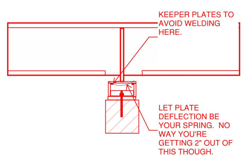
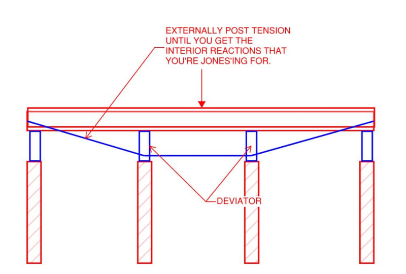
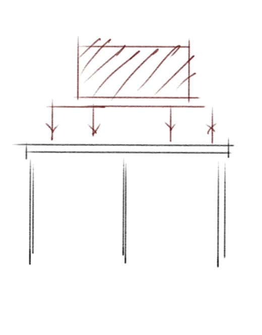
I would like to span a new beam across several existing walls and need the reaction to be relatively uniform. Most of the load is fairly well known dead load. Therefore I'd like to use a spring support. However, I'm not sure what this would actually be. I see various spring supports used for mechanical equipment (the first that comes to find is a canned coil support or vibration springs for large condensers), but was wondering if there is something specifically made to support structural steel. I need a fairly flexible spring, about 6kip/in that can deflect about 2", which likely rules out elastomeric bearing pads. Does anyone know of a product that could be used or has done something similar?

Thanks!

EIT
 
Replies continue below

Recommended for you

Wouldn't the most significant stiffness/flexibility be the supporting beams ?

another day in paradise, or is paradise one day closer ?
 
Not sure what your finish/weatherproofing/envelope is but be careful about this movement leading to damage on those elements
 
You need calibratable springs. One of such is operated through hydraulics. Repost on automotive forum or mechanical forum may get better ideas.
 
I'm not aware of a product quite like that. It may need to be a custom solution, as it's not a very common application.

I'd be careful about that approach unless you're inside a very controlled environment and/or there's a competent and thorough maintenance organization taking care of these. A little corrosion, excess dirt/debris, and other environmental problems could cause your springs to bind and negate the whole exercise. That's assuming you can get a set of springs that flexible to actually behave in a stable configuration.

 
1) What's the situation here?

a) Beam spans?

b) How many spans?

c) What kind of wall?

d) How much space is there available between the beam and these supports?

e) Why doe the beam need to have uniform-ish reactions?

2) Like phamENG, I suspect that this will ultimately prove to be an impractical strategy.

3) Maybe a true, vehicular, spring action shock absorber somehow?

4) I couldn't resist the temptation to try to be creative on this, ergo the sketch below. Fairly predictable but no way in hell you're getting 2" travel out of that kind of setup. You also lose your bottom flange continuity but, if the rest of this would be doable, we could solve that easily enough.

C01_mwz3cc.jpg
 
RFreund:
Look at the std. springs for railcar trucks, the AAR Mech. Dept. is the keeper of all of these stds. They are made to very exacting stds., but only in a specific number of sizes, lengths (free and solid heights), strengths per inch etc. Their ends are ground, tapered and squared, and they would work well for what you are trying to do. The whole process will be quite fiddly as beam stiffness, beam deflection and camber, must all be related to the spring stiffness and a very exacting spring seat height for everything to work out. You can shim the spring seats for some final adjustment. Look up elastic matching, that is essentially what you are trying to do.

Their availability should be fairly good and easy, but you will have to make your own spring seats and guides, and the fixings and guides onto the underside of your beam. I don’t have very current stds. on these, but I don’t think the spring stds. have changed much over the years. Most of these spring sizes come in inner and outer coils which nest together for a higher total cap’y. D2 springs for example, are 8.25” free ht. and 6.625” solid ht.; outer coils are 5.5” o.d. and inner coils are 2&15/16” o.d. The outer coils have a 15.236k solid cap’y. or .586k/16th inch and the inner coils have a 5.15k solid cap’y. or .198k/16th inch of travel. D3 springs have a 9&1/16” free ht. and a 6&9/16” solid ht.; outer coils are 5.5” o.d. and inner coils are 3.25” o.d. The outer coils have a 10.223k solid cap’y. or .256k/16th inch and the inner coils have a 4.103k solid cap’y. or .103k/16th inch of travel. Other spring groups have a somewhat lower cap’y. and greater travel, are softer spring groups. Your local railroad might sell you a sew springs if you knew the right people, and of course, you could always have a spring manuf’er. make a few at a prohibitive cost per spring.
 
Maybe you can look into Belleville washers.

They make some heavy duty cupped washers which you can combine in a multitude of ways to create the spring you are looking for.

 
How accurate do you need to be? And is this permanent or temporary? I think the solution here could be vastly different here depending on the answers.
 
Thanks for all the responses. Some responses:

rb said:
Wouldn't the most significant stiffness/flexibility be the supporting beams ?
Not really, walls/beams that support the new beams are super stiff compared to my new beams even if using the stiffest available steel beam.

Re Kootk:

1) What's the situation here?
- Equipment on existing roof

a) Beam spans?
- New beam would be a continuous 3 span beam - 21', 26', 16' with the equipment in the center span.

c) What kind of wall?
Masonry wall that is supported by a concrete beam

d) How much space is there available between the beam and these supports?
Any distance that we want (it's on the roof)

e) Why doe the beam need to have uniform-ish reactions?
Well, the concrete beam supporting the wall (which supports the new beam), can only handle a about 65% of the simple span reaction. I could side track into talking about the interaction of the brick masonry on top of the concrete beam, but not sure if we need to go down that road yet.

3) Maybe a true, vehicular, spring action shock absorber somehow?
- right, maybe.

4) I couldn't resist the temptation to try to be creative on this, ergo the sketch below. Fairly predictable but no way in hell you're getting 2" travel out of that kind of setup. You also lose your bottom flange continuity but, if the rest of this would be doable, we could solve that easily enough.
- Not a bad idea.

pharmENG said:
A little corrosion, excess dirt/debris, and other environmental problems could cause your springs to bind and negate the whole exercise.
- This got me thinking. Once the equipment is in place and the springs deflect. You could actually lock the springs at that point, right? Seems right, but gets confusing if you were to remove the load and that put it back on. I suppose once you remove it, you'd get a negative reaction at the interior supports.

DH - thanks, very interesting to say the least. Impressive that you have that information. I'll see if I can get anywhere with this.

JLNJ - thanks, I'll into that.


EIT
 
Very solid idea. I'm not exactly sure how I would go about the post tensioning or what the deviator's are, but I probably feel just as comfortable about those 'unknowns' as I do the springs.

EIT
 
RFeund said:
I'm not exactly sure how I would go about the post-tensioning or what the deviator's are

1) Something like a Dywidag all thread bar that you tension by tightening nuts at the end. You're kind of just building a truss and inducing some negative camber in it after the fact.

2) The deviator's just a hinged post or whatever that causes the tendon profile to "deviate" from the beam centroid. Jargon.

I've got a copy of the book shown below which has been useful for detailing and design consideration. If you decide to pursue this strategy, let us know and we can get into that stuff. I've no doubt there are more recent resources available out there as well.

Ingenuity is particularly adept at this kind of thing, certainly in concrete maybe if we say the magic words often enough, he'll magically appear.

Post-Tension, Post-Tensioned, Post-Tensioning, Post Tension, Post Tensioned, Post Tensioning, Prestresssed. There, all good.

C01_fbc7le.jpg
 
this does sound awfully complicated and technical (and expensive?).

what is driving you to want to distribute the reactions in such a careful manner ? The obvious driver is bending moment in the beam ?

would it help to make the beam discontinuous … several SS spans rather than one continuous beam ?

surely there are several competing loadcases that apply load in different places ?

another day in paradise, or is paradise one day closer ?
 
I've seen KootK's latest proposal accomplished to reinforce some giant existing wood trusses in an old hanger. They used aircraft cable and turnbuckles to adjust the tensioning.
 
RFreund:
When you make the 63’ beam continuous over three spans, and then load the center span, there will tend to be uplift reactions out at the two outer support points. And, this will just tend to draw more reaction (shear) to the two inner walls. This sounds like just the opposite of what you are trying to accomplish, even with some elaborate reaction adjustment scheme. Alternatively, if you span the outer 21’ & 16’ spans with simple beams to the inner walls, and then span the middle space with a 50’ long simple beam (some such length), resting on the lower two outer simple beams, the upper beam will react outside (beyond) the centers of the two lower beams, and transmit more than half its reactions to the outer most support points; without a bunch of fancy gymnastics. Play with the length and longitudinal positioning of the upper beam, and your wall reactions become more straight forward. We do this sort of thing often on heavy haul trailers and railcars to adjust the wheel/axle loadings.

Jayrod12:
You are better off using solid rods threaded at the ends. They stretch (extend) much less than wire rope for the same applied force, and you can actually find turnbuckles long enough to provide the length take-up. Wire rope wires have essentially the same modulus of elasticity as the solid rod, but the entire stranded cable also has a significant mechanical elongation as the wires and strands adjust (tighten around each other) themselves to loading.
 
Oh, I'm aware, I'm just indicating what I've seen in use. In this instance it allowed the deflectors to be nothing more than a piece of round tube welded to a plate on each side of the truss bottom chord with a bunch of through bolts. I honestly thought it looked fairly slick and after 20 years was still holding the roof together.
 
dhengr, that’s a great idea with the sub-framing to control the reactions. Also good note about the cable stretch and it’s reduced effective modulus - just wanted to add that pre-stretched wire rope is available if needed and will increase the effective modulus of the cable.
 
I’m sure there’s some optimum layout of a subframe on top of the beam which would balance your reactions..? You’d need a number of iterations but it could be done without expensive springs requiring ongoing maintenance etc. Its late here so tell me if I’m going crazy!!

406CF9F7-82C3-4210-836C-39A3672873EB_thndbn.jpg
 
DH - how did I not think of that!! Great call. I really missed the forest for the trees on this one. I'm fairly certain some sort of sub framing should work. Thank you.

MIStructE_IRE - Also thank you. You and DH are basically saying the same thing.

EIT
 
Status
Not open for further replies.

Part and Inventory Search

Sponsor