Continue to Site

Eng-Tips is the largest engineering community on the Internet

Intelligent Work Forums for Engineering Professionals

  • Congratulations KootK on being selected by the Eng-Tips community for having the most helpful posts in the forums last week. Way to Go!

BEAM SPLICE NOT ON POST?? HELP! 1

Status
Not open for further replies.

evolvingdesigns

Structural
Feb 23, 2021
10
THE FRAMER DIDN'T SPLICED THIS (2) 2x12 BEAM ON THE POST, NOW THE CODE OFFICIAL WON'T SIGN OFF UNTIL ITS FIXED, ANY SUGGESTIONS ON HOW TO FIX IT?
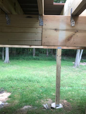
IMG_80761_srb2p8.jpg
 
Replies continue below

Recommended for you

Is that the only thing you see wrong here?

1) where's the bridging between joists over bearing?
2) beam splice in the wrong place
3) no lateral stability in the connection between the post and the beam
4) why is there a 2x4 plate under the beam? To give them something to support the beam on while they spliced it?

How do you fix it? You either remove the framing that was installed incorrectly, or you add a support under the splice on a new foundation. Also, address the items I listed above.

EDIT: just occurred to me that the post may be in the background. The perspective is a little funny in that picture.
 
the image is deceiving...They are 6X6 posts, the post you see IS under the beam beyond

Put a post under the splice. If that isn't possible, remove the section with the splice back to the nearest post on either side and install new unspliced beam across the span that is supported by said posts.
 
Is the splice at the same location for both plies?
 
Brand805
the splice is not both plys...regardless it should bear on the beam
 
Are we looking at to girders? One in the near frame and one where you can see just the bottom two inches in the far frame?

That photo is definitely deceiving.

Why does the splice need to be over the post? Celt83s solution might just be the ticket.

 
I've never seen a Simpson HCA hinge connector installed, does anyone have a pic?
 
The HCA is a neat connector...but probably not practical in this situation. It's intended for use in roof framing, so it's painted carbon steel. Not an ideal material choice for what appears to be an outdoor deck. To use it, you'd have to rip up the decking and cut the beam to make it fit. That will probably be done with a a recip saw and with about as much accuracy as an ax. Then you have to consider that those are custom order products, and here in the mid-atlantic most contractors are telling me the lead times on Simpson products are almost as bad as the rest of the market. So a couple bags of quikcrete, top and bottom post connectors, and a 6x6 will probably be faster and cheaper with a better end result.

Or, if the inspector will okay it, adding a third lamination on the side with the continuous 2x12 and putting Simpson DJT brackets at the posts to get minimum bearing for that ply and it's probably the cheapest and easiest. You may have to prove that the post can take it as an eccentric load, though.
 
Can you nail a couple of 3/16" straps on a slope and use glulam rivets?

Rather than think climate change and the corona virus as science, think of it as the wrath of God. Feel any better?

-Dik
 
How deep are the piers? It might be easiest to just add a post under the splice?
 
No, its an optical illusion, the post you see in the photo is in the distance
 
Please post better photos and/or a sketch.

That post looks very small for the size of the beam. And no lateral support.
 
SWComposites its an optical illusion, that post is a 6X6 off in the distance
 
i thought this forum was for engineers to discuss technical matters, not a forum for engineers to attempt in vain to rescue the general public from their idiocy based on a very questionable photo?
 
Add new support under or lap some timbers onto the splice.
 
evolving designs,

If those beams are 2 x 12's, as labeled, ( approx. 11 1/2" deep/wide) there is no way the posts are 6" x 6".


Jim


Once again, the post seen in the photo has nothing to do with the beam in question. The post is off in the distance, supporting a different beam. Ignore it.

evolvingdesigns, there's no secret method to uncover, midspan beams splices are not okay. It's technically possible to transfer the moment from that ply into a scab, then back in on the other side of the splice (with at least 15 lag screws + a few feet on each side), but wood moments connections are not a good idea to begin with, and especially not in exterior exposed members of a deck. At least with a deck, there's no finish materials to be redone. Either put in a column and footing under the splice, run a full length sister next to it, or rip out that ply and replace it with a full length member. You see mid-span splices all the time in residential wood framing, and contractors need to understand that doing so makes that ply useless in bending. No better teacher than having to demo and rebuild it correctly.
 
You need to hire a structural engineer to review this. As pham pointed out, there is more than just the splice that isn't properly done.
 
Status
Not open for further replies.

Part and Inventory Search

Sponsor