Deener
Mechanical
- Aug 30, 2018
- 49
Hey guys,
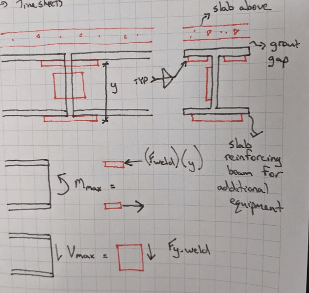
Contractor is requesting to splice a beam for easier installation access. These beams are placed below a slab (grout gap) and are used to support the existing slab for additional equipment (heat exchangers). The contractor has requested the following splice. All fillet welds occurring in place in the field. Although this is a splice detail I'm not used to seeing, as long as the welds and splice plates are properly sized,I see no issue with this design. Flange splice plates react the maximum moment in the beam with a couple and put the splice fillet welds in shear. Single web splice plate transmits the peak shear in the beam through a fillet weld. Beams will be installed with a nominal gap of no more than 1/8" if any. From a design perspective, specifying a CJP weld would be much easier but I suspect not as practical.

Thanks in advance!
Contractor is requesting to splice a beam for easier installation access. These beams are placed below a slab (grout gap) and are used to support the existing slab for additional equipment (heat exchangers). The contractor has requested the following splice. All fillet welds occurring in place in the field. Although this is a splice detail I'm not used to seeing, as long as the welds and splice plates are properly sized,I see no issue with this design. Flange splice plates react the maximum moment in the beam with a couple and put the splice fillet welds in shear. Single web splice plate transmits the peak shear in the beam through a fillet weld. Beams will be installed with a nominal gap of no more than 1/8" if any. From a design perspective, specifying a CJP weld would be much easier but I suspect not as practical.

Thanks in advance!

