Eng-Tips is the largest engineering community on the Internet

Intelligent Work Forums for Engineering Professionals

Beam Splice - Welded with Limited Access 4

Status
Not open for further replies.

Deener

Mechanical
Aug 30, 2018
46
0
0
CA
Hey guys,
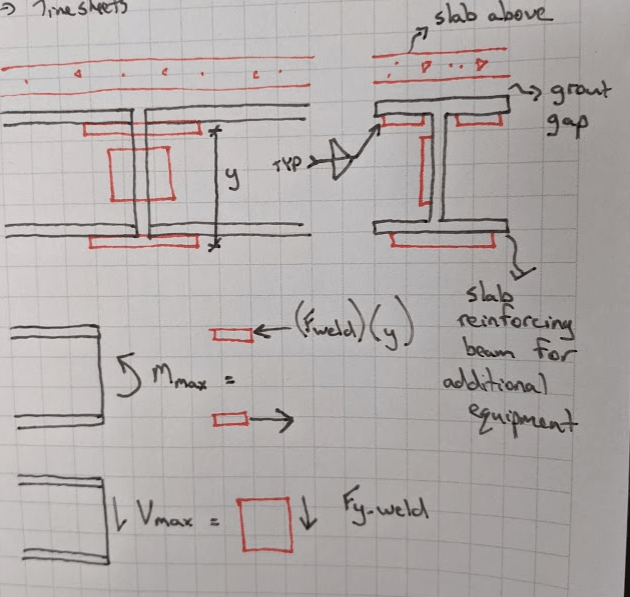
Contractor is requesting to splice a beam for easier installation access. These beams are placed below a slab (grout gap) and are used to support the existing slab for additional equipment (heat exchangers). The contractor has requested the following splice. All fillet welds occurring in place in the field. Although this is a splice detail I'm not used to seeing, as long as the welds and splice plates are properly sized,I see no issue with this design. Flange splice plates react the maximum moment in the beam with a couple and put the splice fillet welds in shear. Single web splice plate transmits the peak shear in the beam through a fillet weld. Beams will be installed with a nominal gap of no more than 1/8" if any. From a design perspective, specifying a CJP weld would be much easier but I suspect not as practical.

image_nagxmq.png


Thanks in advance!
 
Replies continue below

Recommended for you

I believe the weld for the top splice will be difficult to perform on the web side. Is you weld symbol correct? Do you want "weld all around" or just at the ends. If just at the ends, you can ignore my post.
 
Good point XR250 (Honda ref?). My drawing isn't to scale. I'll confirm accessibility with the contractor. There will have to be a weld in there.
 
If accessibility is a problem on that side, you could investigate plug welds along the plate. Still won't be easy, but it might be easier.
 
What's your gap for the grout at the top of the beam? Instead of two plates under the flanges you could always use a plate above the beams. It would rely on only longitudinal welds so shear lag would need to be checked, but it would be easier to build.
 
XR250,

Weld symbol shown seems to be double-sided fillet weld - opposite edges of plates to flanges/web. Not sure where you got "all-around" from.

Deener,

Suggest that the shear splice plate be rotated 45 deg (oriented as a diamond) to minimize the overall dimensions of the plate.

As altenative, if practical, I would also think hard about CJPing at least the web and the bottom flange and turn the plates shown into simple backers as the weld positions would be easier. Would make accessing the top flange connection less problematic, IMO.
 
What is current code requirement on beam splices - only needs to develop maximum design moment, or to the capacity of the original shape? Also, due to the gap in between the beam segments, the structural properties have changed, how are you going to check beam deflection for the configuration shown? I don't think the problem is such simple, though numerically it works.

I'm also curios about the grout required for this type of construction. What is the construction sequence, erect the beam and cast the concrete slab, or vice versa? If the former, shouldn't the beam should be spliced prior to forming?
 
retired - since it's a retrofit to support the load imposed by new equipment above, I'd think it's probably just a matter of capacity equaling or exceeding demand.

For deflection, I don't think I'd worry too much. As long as enough moment and shear are transferred through the joint, I wouldn't expect any noticeable deflection discontinuities.
 
phamENG,

You've a good point, but I'm confused, was the beam originally a one piece steel, or was the two pieces without connection the original design?
 
OP will need to say for sure, but it sounds like one beam with no connections bu the contractor asked for a splice to help with constructability.
 
phamENG,

Yeah, the OP needs to tell more. Your "guess" sounds like change of design to me. May not be critical, but...
 
Okay, I guess this beam is an addition for the weight of the new heat exchanger only. One piece would be too heavy for lift into place. But then, given that much trouble for this setup, wouldn't it be easier to provide a skid on the floor to spread out the load, if space and head room permit.
 
Originally the beam was continuous. This is a retrofit and the slabs were not originally designed to take the additional weight of the heat exchangers so these are reinforcing beams. The contractor is requesting the splice because it will be nearly impossible to get the long continuous beam into the room where it will be lifted. phamENG is correct. The splice will be designed to meet the original capacity of the beam.
jdonville - I agree with your opinion about specifying a CJP on the web and bottom flange. I think the contractor is hoping to use less weld with the fillet. I've never thought of orienting a splice plate like that to optimize the size of the plate. Cool thought.
 
Deener said:
Contractor is requesting to splice a beam for easier installation access.

Did the Contractor request a certain location for the splice? If splice can be located away from high-moment area of the beam, splice detail becomes less important. Many times, as long as the beam can be put in place, length of the two segments is not important to the Contractor. Ask.

[idea]
 
I think SRE is correct. My impression is the original beam is still there as one piece (never been touched), this is an additional reinforcing beam for the slab to support the added weight. If so, the location of joint shouldn't be matter, but personally I don't think this detail would qualify the beam as continuous, albeit there is moment capacity.
 
XR250, in response to your post above (for some reason the forum is not letting me quote you directly):

I am trying to figure out if MR_E30 is a BMW reference (the best car ever built)

Yes, the hunt for an answer is over. The M and R are my initials, and E30 is most definitely a reference to the greatest car of all time, the BMW E30. My username is also the custom license plate I started using in 2004, which I still retain to this very day.

I've had almost a dozen over the years. The most recent started life as a 1991 318is, but was modified to feature a supercharged S52 (Rotrex C30 SC), 5-lug swap, coilovers, cage, crazy drivetrain upgrades for the increased power, among many, many other things. It was an absolute monster that always left a smile on my face.

If you're an E30 guy let me know, as we may have already met at some point on another forum, as I have been on R3vlimited since 2004.

Now back to the OP and his question!
 
Is a bolted splice out of the question? You may also consider using round bar, this will make the welding easier and will be easier for QC. Maybe even a combo of web plates & round bar.

Beam_Splice_xo98yr.jpg
 
Hello all,
what are the different arrangements to provide splicing to beam? It's required to remove top flange splice as the top flange is supporting a deck. So can anyone suggest me how can i provide splice at top to take the tension coming there due to moment?
Thank You
 
Status
Not open for further replies.
Back
Top