Eng-Tips is the largest engineering community on the Internet

Intelligent Work Forums for Engineering Professionals

  • Congratulations waross on being selected by the Eng-Tips community for having the most helpful posts in the forums last week. Way to Go!

Beam to column connection with eccentricity 4

Status
Not open for further replies.

Mike1998

Structural
Oct 5, 2018
9
NL
Hi all,

I have a question regarding a beam to column (hinged) connection (see the attached file).

The beam transmits a reaction F to the flange of the column with an eccentricity e from the centerline of the column. Should I check the column with a bending moment M = F*e?

Thank you in advance.
 
 https://files.engineering.com/getfile.aspx?folder=bf046b00-f4b7-481d-9bdc-ab6cd2821e05&file=column.jpg
Replies continue below

Recommended for you

human909 said:
Damn you does that mean that since I agreed with you earlier I need to flip flop too?

We'll see how it goes. I'd be grateful if you'd help me vet it.

THE THEORY

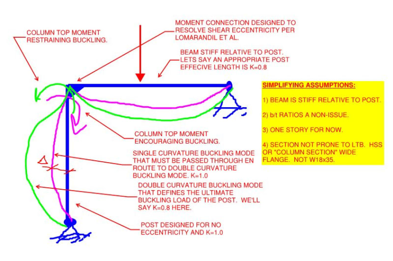
1) Model per the sketch below.

2) Make a bunch of simplifying assumptions that I feel are pretty reasonable for a gravity post.

3) I contend that the process of column buckling may be envisioned as occurring in two phases:

a) Magenta; single curvature; [K = 1.0]; column top moment encourages buckling; design case; load eccentricity to RIGHT of post centerline.

b) Green; double curvature; [0.7 < K < 1.0]; column top moment restrains buckling; ultimate buckling capacity; load eccentricity to LEFT of post centerline.

At the limit of the single curvature mode shape, the apparent flexural stiffness of the post drops to zero for the single curvature buckling mode. This causes it to kick to the left until it engages the stiffness of the beam as rotational restraint.

4) In transitioning from magenta to green, the post must pass through a moment in time where [e = 0; K=1; design case]. Moreover, after the post passes through this moment in time, it's capacity continues to increase. So this moment in time represents a lower bound on in-plane buckling capacity.

5) I see one hiccup with #4. At the moment in time described, the column is not yet shifted to the left enough to reach equilibrium. Another way to look at it is that it's an [e = 0; K = 1.0] design with a baked in displacement, delta, that adds to the normally assumed column imperfections. So the "moment in time" column capacity is some degree lower than that calculated at [e = 0; K = 1.0]. I feel that the impact of this is going to be small will relatively stiff beams and larger with relatively flexible beams since, the larger the beam stiffness, the less movement is required to re-establish equilibrium.

SOME TAKEAWAYS

I feel that this theory supports some of the limitations that many engineers are already applying as a matter of intuition and judgment. Namely, if one is going to ignore the eccentricities in a gravity post in favor of a nominal moment connection:

1) It should be a stocky, post appropriate section like an HSS, W14, etc. It should not be a W12x14, W18x35, or anything else with relatively narrow flanges and an affinity for LTB.

2) The [EI/L] of the beam(s) should be relatively stiff compared to that of the post. No limp noodles, no joist seats unless the BC ties in too.

C01_iffjwk.jpg
 
Agent said:
Yes, very easy to get unbalanced moments when you consider for example 0.9G on a beam one side and 1.2G + 1.5Q on the other beam opposite.

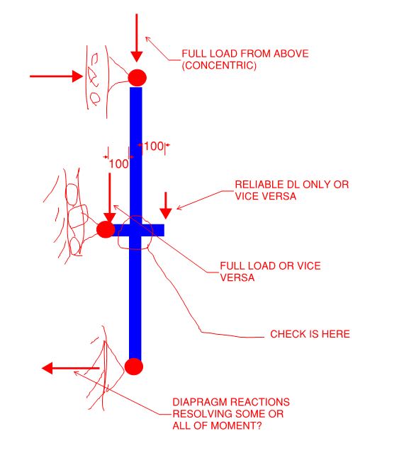
This is based on net stabilising and destabilising effects and how they impact on the worst-case scenario for the column, most codes have some similar requirement. This is the requirement required to be considered in AU & NZ codes, least my interpretation of it. Assume 1.2G+1.5Q load from above, load below is load above +0.9G from one beam, +1.2G+1.5Q from other beam. Work out worst case out of balance load based on highest beam reaction minus the lowest, apply the 100mm eccentricity from face of column. Check column for axial load and the bending from unbalanced eccentricity moment. This is usually more critical than taking the net unbalanced moment generated from full load on both beams (even if the axial load is slightly higher if you were to do this). Check all columns top down in this manner.

As well as above whilst we are on column design, if in a seismic region check the actions resulting from deformation compatibility in addition to eccentric moments, obviously if these columns are attracting axial loads form the seismic system this case can govern over and above the gravity ultimate limit state cases.

Of course we have to consider this load case, at least implicitly. I would wager that even those modelling the eccentricity aren't going to this level of detail though, at least for all columns. Since you're basically removing all the live from one side of the column and a chunk of dead, for gravity columns you might as well be removing half the demand from the column. Are there cases where removing half the demand from the column and adding this eccentric load are critical? Yes, and those cases are the cases I'd be checking the eccentric moments, but 90% of the time, by inspection this will not control. Generally, following good practice for columns (W8, W10, W12, W14 that are roughly square) means that this won't control in most cases.
 
Just removing live load from one beam supported by the column virtually leaves the axial Load unchanged in multistorey scenarios. Its not something that I would model. Just applied by hand when I'm doing the design checks. So you're ending up checking for say 95% of the axial load and the worst eccentric moment you can derive. Most of the time it probably doesn't govern, sometimes it probably does. But the point is that it is checked irrespective. The thread is about whether you should be checking it in the first place after all.

Of course for a multistorey building the axial load barely changes when you drop a small overall proportion of the live load from a single member, for single or double storey it's another matter of course. Totally depends on the scenario, I'm in the make some simple conservative assumptions & check it and see camp, takes just as long to check either way if your design tools/methods are up to scratch. It's not as onerous as people make out, and to me it's better than almost ignoring completely as some folks advocate.

 
@Agent666: I'd like to ensure that understand your method accurately. Is the model shown below correct?

Beyond a certain height, it's been my experience that columns pretty much just stop caring about the moments induced at individual floor levels other than, perhaps, code minimum eccentricities on the axial load as a whole. As you said, though, it depends on the scenario.

C01_hr3p8f.jpg
 
Yeah that's more or less what the standard says to do. Simply looking at each level in isolation to determine the eccentricity moment. All other actions from other calcs, analyses, etc superimposed.

 
I think I have to retract my earlier statement ("What is left to design for the column?").

I implied that creating a load path for eccentrically applied loads to be transmitted to the column centroid removed the need to design the column for the net moment from that eccentricity. However, that implies that the column would not see any moment along its length. And I can't rectify that in my mind. Certainly, with typical detailing, column moments must exist (due to unbalanced spans, pattern loading, etc.)

----
just call me Lo.
 
I have always believed that the columns should be designed for the unbalanced eccentric moments. Some argue that there is enough fixity in the connection that for the magnitude of moments under consideration the system is acting like a fixed beam, which effectively carries the beam reaction to the center of the column; but that means that you have to design your connection to be capable of doing that (or you must verify that your connection has that additional capacity). The moment doesn't just go away. And as was indicated in several of the posts, some codes explicitly require that you consider the eccentric moment in the design of the column. You may be interested to know that the RAM Structural System software automatically and explicitly accounts for the unbalanced moments. The program 'skip loads', or pattern loads, the Live load on the beams around the column, determining the resulting unbalance moments and the associated axial load (reduced because of the load skipping). And it does this for the top of the column and the bottom of the column to get the worst case of single curvature vs double curvature. The result is that for each load combination the program investigates 34 permutations of full and skip load conditions. Knowing that I have explicitly accounted for this, I am much more comfortable designing columns with a demand/capacity ratio approaching 1.0, which means a more economical structure. And it has been my experience that contractors grade engineers based on the steel weight, and seek out those engineers that consistently deliver the lighter designs.
 
Status
Not open for further replies.

Part and Inventory Search

Sponsor

Back
Top