Continue to Site

Eng-Tips is the largest engineering community on the Internet

Intelligent Work Forums for Engineering Professionals

  • Congratulations KootK on being selected by the Eng-Tips community for having the most helpful posts in the forums last week. Way to Go!

Beam with cantenery action

Status
Not open for further replies.

JAE

Structural
Jun 27, 2000
15,444
We have a project where we are checking a long steel tube that is on top of a steel plate wall - essentially the tube is the wall cap that goes around the perimeter (4 walls) of a steel tank.

The tank is filled with water and imparts lateral pressures on the tank's four walls. This creates an outward uniform force on the tube on all four sides.
The tank is about 10 ft. wide x 36 ft. long.

The tubes will naturally bend outward and have axial tension in them due to the orthogonal walls with their outward uniform load.

The question is - we need to determine the stress in the long 36 ft. tube due to axial, bending and perhaps any axial effect from what appears to maybe be a cantenary effect. How to do this?

Roark's has essentially a case where a beam is rigidly fixed at the ends with a uniform load on it.
It is labeled as Table 8.10, item 3 (Beams restrained against horizontal displacement at the ends - ends pinned to rigid supports, uniformly distributed transverse load on entire span.

However, the end walls of this tank are not perfectly rigid and will bow inward a bit with the cantenary tension on the long tube, right? So this will have the effect of reducing the axial tension in the tube a bit. Roark's does NOT have an item with axial spring supports at the ends.

We've modeled this in RISA 3D and get results but something tells me that the RISA results may not include non-linear effects of the cantenary action in this tube due to variations of the end supports with regard to axial loads.

I seem to understand that RISA does PDelta analysis but that only includes PDelta effects perpendicular to the member and does not include axial PDelta effects.

Any thoughts on this? I've inserted essentially the beam problem in a sketch.
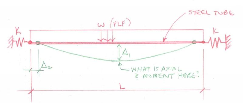
Tube_Cap_Sketch_lqk13h.jpg


Check out Eng-Tips Forum's Policies here:
faq731-376
 
Replies continue below

Recommended for you

JAE, if you are really interested in a beam with axial springs, why not use Roark's formulae for beams with simultaneous axial and transverse loading?
To do so, you need to iterate on the axial load by calculating the shortening of the beam due to the transverse deflection. This calculation is however not in the Roark, but you can use this sheet from xcalcs.com
However I don't understand why you don't treat it as an edge beam to a flat plate?

prex
[URL unfurl="true"]http://www.xcalcs.com[/url] : Online engineering calculations
[URL unfurl="true"]https://www.megamag.it[/url] : Magnetic brakes and launchers for fun rides
[URL unfurl="true"]https://www.levitans.com[/url] : Air bearing pads
 
thank you for the info handofthelion. I learned how to use Abaqus years ago, which sounds like more of a comparable program to what you used.

JAE, I mainly asked handofthelion this because I suspected that RISA isn't capturing any catenary effects at all. I've been down this road before with a different problem but looking for the same effect using RISA and similar programs. I think thats probably why you're not feeling like RISA is giving you the true answer.

In your first post you stated "So this will have the effect of reducing the axial tension in the tube a bit". I don't think the axial tension (or at least the component perpendicular to the adjacent wall) can change. On the 36' tube, the tension should be 1/2*W*10', and the 10' tube should have a tension of 1/2*W*36'. Where W is the uniform reaction at the top of the tank wall.
 
Thanks for all your input.

Yes, we were concerned with the fact that RISA doesn't do PDelta with the axial component of the member.

The tank is only about 5.5 ft. tall and 8 ft. x 36 ft. in plan. This is an actual tank that was built and filled with water - then began failing with excessive outward bowing.
We needed to verify the behavior and understand the progress through loading, yielding in some areas, and initially I was concerned about the axial component that was "missing" from the RISA model.

It turns out that the stresses are way above yield such that we could properly discount the axial component of the member as the end walls would essentially bow inward (i.e. the end springs I show in the sketch above have small "k" values).

The tank sides are a corrugated deck-like system so in plane they are just accordions as the welding is on the outer faces of the decking and allows the tapered deck sides to move relative to the tube.

So the discussion above is all helpful and valid for the theoretical treatment but for this particular project - the numbers overwhelm any subtlety in the second order axial numbers.

Check out Eng-Tips Forum's Policies here:
faq731-376
 
If the water is 5' deep, w = 260#/'.
M = 260(36)[sup]2[/sup]/8 = 42,120'#

If the member cannot resist the above moment, it could try to act as a cable. Then, if Δ[sub]1[/sub] is L/36 = 1', the tension would be 42,120#. Depending on Fy, the member would need an area in the order of 2.0in[sup]2[/sup] to resist axial tension. Apart from having a low "k" value, the end springs may not be strong enough to resist such a large horizontal force.


BA
 
"excessive outward bowing" ... at about mid depth at the centre of the long side ?

sorry, but can't see the short sides bowing inward ?

how'd the corners behave ? with sandwich side side-walls I'd expect a joint on both faces, or only one ??

I'm not sure how effective this tie-rod around the top edge would be in helping the walls react pressure. I'd've added (vertical) beams on the long sides.

I guess you could run the tank without the tie-rod, and with. If RISA is missing some axial load you could estimate this by the change in length. I wonder what happens to the tie-rod in the corners ??

another day in paradise, or is paradise one day closer ?
 
The outward bowing was about 12 to 16 inches per the owner.
They then took out the water and the permanent outward bowing is now 1 1/2" or so.

The end walls appeared straight but they were only 8 ft. long.

BAretired - not sure we would generate that much axial load as the end walls would simply bow inward (not much stiffness there) and the large axial loads just wouldn't be possible....thus my end springs in the drawing I posted above. Infinite rigidity (a pin support) creates way more load than a spring condition with minimal stiffness.

Analysis suggested that the tubes on top of the 36 ft. long wall yielded first at the corners, then secondarily at midspan.


Check out Eng-Tips Forum's Policies here:
faq731-376
 
thx. don't really get the end support issue. I'd consider the tie-rod as that, a tension member, rather than as a beam with axial restraint and lateral load.

the corner of the tie-rods will always give you trouble, as the tension load tries to straighten out the corners (and ovalise the rectangle).

another day in paradise, or is paradise one day closer ?
 
any cross-bracing in the middle?

Dik
 
dik said:
any cross-bracing in the middle?

How about three straight tension ties 8' long, dividing the side members into four nine foot spans?

BA
 
No cross bracing at all.
Can't really do tension ties as this is a swimming pool believe it or not.
Originally a large shipping container cut in half longitudinally and then reinforced to serve as an open tank-pool.


Check out Eng-Tips Forum's Policies here:
faq731-376
 
how about tension ties around the outside ? like running a cable around the damn'd thing.

if you want to make it look respectable ... cables on each side, with eyes at both ends, pins joining the cables together, turnbuckles in the middle of each cable to tension them. Maybe at 2/3 depth and 1/3 ?

another day in paradise, or is paradise one day closer ?
 
I think the cheapest would be to slap up an additional perimeter set of tubes to supplement the undersized existing tubes.
That way the interior pool area is not interrupted and the work is all on the outside.

Thanks for the suggestions.

Check out Eng-Tips Forum's Policies here:
faq731-376
 
rb1957 said:
how about tension ties around the outside ? like running a cable around the damn'd thing.

if you want to make it look respectable ... cables on each side, with eyes at both ends, pins joining the cables together, turnbuckles in the middle of each cable to tension them. Maybe at 2/3 depth and 1/3 ?

That will not work unless the end walls can resist the tension in the long cables. And even if they could, the long cables would deflect substantially under load.


BA
 
BAretired said:
If the member cannot resist the above moment, it could try to act as a cable. Then, if Δ1 is L/36 = 1', the tension would be 42,120#. Depending on Fy, the member would need an area in the order of 2.0in2 to resist axial tension. Apart from having a low "k" value, the end springs may not be strong enough to resist such a large horizontal force.

JAE said:
BAretired - not sure we would generate that much axial load as the end walls would simply bow inward (not much stiffness there) and the large axial loads just wouldn't be possible....thus my end springs in the drawing I posted above. Infinite rigidity (a pin support) creates way more load than a spring condition with minimal stiffness.

I know this has been more or less solved on JAE's end. But just on the issue of the tension in the 36' long tube; I don't think the spring stiffness or deflection has anything to do with it. If the water is 5' deep and the reaction at the top wall is 260 lbs/ft, then the reaction at the end of the 10' tube is 1/2x10'x260lbs/ft = 1300lbs. Maybe I'm over simplifying this, but I don't see how the tension in the 36' tube can be any more or less than the force created by the water acting on the 10' segment of wall. With that said, the tension in 36' long tube appears to be insignificant compared to the bending.
 
I agree. My solution involved constant tension for the same reason.

I like to debate structural engineering theory -- a lot. If I challenge you on something, know that I'm doing so because I respect your opinion enough to either change it or adopt it.
 
CANPRO, I agree that, if the members act as a beam in bending, the reaction from the 10' and 36' long members would be 1300# and 4680# respectively.

I did not know the size of the members, but it was clear from the OP that the 36' long members were too small to act as a beam. As an approximation, I assumed that they had zero bending strength and carried the load as a cable. In order to do that, the corner posts had to resist an axial force in the long members. The magnitude of the axial force at midspan is the bending moment 'M' of a 36' beam divided by its sag. In this case, sag is measured horizontally.

M is 260*36*36/8 = 42,120'#. If the sag of the member at midspan is assumed to be one foot, the axial force at midspan is 42,120#. If the sag is 2', the axial force is only 21,060#. The horizontal reaction going into the corner post would be the axial force minus 1300#.

KootK, I'm not quite sure with whom you are agreeing but the tension in the 36' long member, while nearly constant, is not constant. It is slightly greater at the ends than at midspan because of the slope.


BA
 
the corner post could be a reinforcement added to the side walls.

As the cables on each side make a ring, could the reaction from the long sides be reacted by the cables on the short sides, and vis versa; naturally increasing the tension in each.

I thought you could analyze the side walls as plates, without the cable supports, and this'd tell you the maximum deflection, which'd tell you the change in length and so the tension in the cable. Clearly adding this to the structure relieves the side walls somewhat.

another day in paradise, or is paradise one day closer ?
 
rb1957 said:
As the cables on each side make a ring, could the reaction from the long sides be reacted by the cables on the short sides, and vis versa; naturally increasing the tension in each.
Cables on all sides make a ring, but the reaction from the long sides is acting at 90[sup]o[/sup] to the reaction from the short sides, so neither has any effect on the other.

BA
 
@JAE: I modeled this in STAAD and it became more of a arching action thing than anything else. I did a beam with moments released and horizontal springs at the end. To initiate the arching action (i.e. axial load), I introduced a bit of imperfection (about 0.5") at mid span and did a P-Delta (the P-Delta didn't have that big of an impact as far as I can tell). The key factor in reducing moment in the beams and getting axial force was the stiffness of the horizontal spring: the stiffer it was the less moment developed and the more axial load there was. This was the case regardless of how much initial imperfection I introduced.

So I guess the question is: are your end supports really stiff enough develop the kind of axial forces you are concerned about?

(And sorry I was late to the party.....been on vacation for about the last 4 days.)

 
Status
Not open for further replies.

Part and Inventory Search

Sponsor