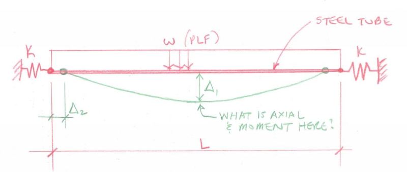
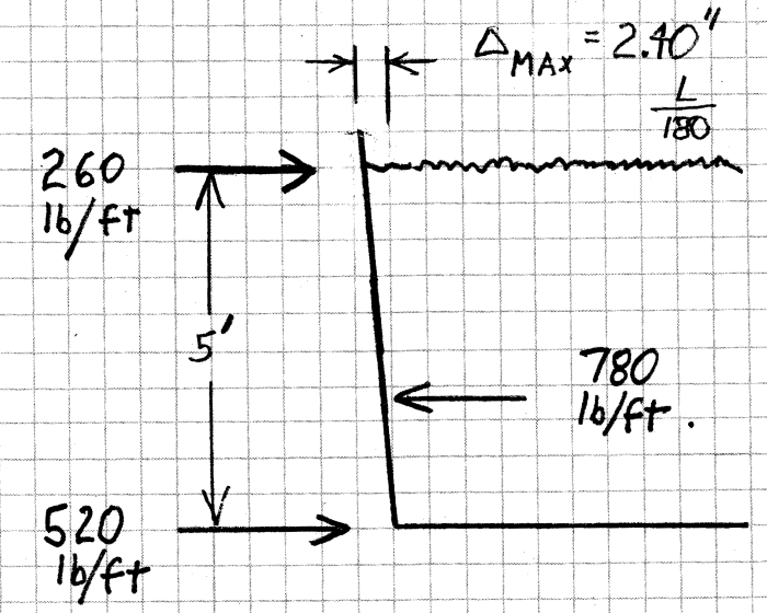
We have a project where we are checking a long steel tube that is on top of a steel plate wall - essentially the tube is the wall cap that goes around the perimeter (4 walls) of a steel tank.
The tank is filled with water and imparts lateral pressures on the tank's four walls. This creates an outward uniform force on the tube on all four sides.
The tank is about 10 ft. wide x 36 ft. long.
The tubes will naturally bend outward and have axial tension in them due to the orthogonal walls with their outward uniform load.
The question is - we need to determine the stress in the long 36 ft. tube due to axial, bending and perhaps any axial effect from what appears to maybe be a cantenary effect. How to do this?
Roark's has essentially a case where a beam is rigidly fixed at the ends with a uniform load on it.
It is labeled as Table 8.10, item 3 (Beams restrained against horizontal displacement at the ends - ends pinned to rigid supports, uniformly distributed transverse load on entire span.
However, the end walls of this tank are not perfectly rigid and will bow inward a bit with the cantenary tension on the long tube, right? So this will have the effect of reducing the axial tension in the tube a bit. Roark's does NOT have an item with axial spring supports at the ends.
We've modeled this in RISA 3D and get results but something tells me that the RISA results may not include non-linear effects of the cantenary action in this tube due to variations of the end supports with regard to axial loads.
I seem to understand that RISA does PDelta analysis but that only includes PDelta effects perpendicular to the member and does not include axial PDelta effects.
Any thoughts on this? I've inserted essentially the beam problem in a sketch.

Check out Eng-Tips Forum's Policies here:
faq731-376
The tank is filled with water and imparts lateral pressures on the tank's four walls. This creates an outward uniform force on the tube on all four sides.
The tank is about 10 ft. wide x 36 ft. long.
The tubes will naturally bend outward and have axial tension in them due to the orthogonal walls with their outward uniform load.
The question is - we need to determine the stress in the long 36 ft. tube due to axial, bending and perhaps any axial effect from what appears to maybe be a cantenary effect. How to do this?
Roark's has essentially a case where a beam is rigidly fixed at the ends with a uniform load on it.
It is labeled as Table 8.10, item 3 (Beams restrained against horizontal displacement at the ends - ends pinned to rigid supports, uniformly distributed transverse load on entire span.
However, the end walls of this tank are not perfectly rigid and will bow inward a bit with the cantenary tension on the long tube, right? So this will have the effect of reducing the axial tension in the tube a bit. Roark's does NOT have an item with axial spring supports at the ends.
We've modeled this in RISA 3D and get results but something tells me that the RISA results may not include non-linear effects of the cantenary action in this tube due to variations of the end supports with regard to axial loads.
I seem to understand that RISA does PDelta analysis but that only includes PDelta effects perpendicular to the member and does not include axial PDelta effects.
Any thoughts on this? I've inserted essentially the beam problem in a sketch.

Check out Eng-Tips Forum's Policies here:
faq731-376


![[idea] [idea] [idea]](/data/assets/smilies/idea.gif)
![[r2d2] [r2d2] [r2d2]](/data/assets/smilies/r2d2.gif)