Continue to Site

Eng-Tips is the largest engineering community on the Internet

Intelligent Work Forums for Engineering Professionals

  • Congratulations SSS148 on being selected by the Eng-Tips community for having the most helpful posts in the forums last week. Way to Go!

Bearing Housing Roundness 2

Status
Not open for further replies.

TugboatEng

Marine/Ocean
Nov 1, 2015
11,812
I'm looking for some thoughts on bearing housing roundness. I have a cylindrical roller bearing that a housing fit tolerance of 0.001-0.009" and my housing measures at 0.004-0.013.
 
Replies continue below

Recommended for you

> Bearing Housing Roundness

I was trying to figure out roundness requirements myself the other day.

Let's look at the SKF Bearing Maintenance Handbook

skf said:
Dimensional, form and running accuracy requirements

The accuracy of cylindrical bearing seats on shafts and in housing bores should correspond to the accuracy of the bearings used. SKF recommends the following guidelines for form and running accuracy when machining seats and abutments.

Dimensional accuracy
For bearings made to Normal tolerances, the dimensional accuracy of cylindrical seats on the shaft should be at least tolerance grade IT6. The
dimensional accuracy of the housing should be at least tolerance grade IT7

Note the IT classes are included in appendix C. IT7 would end up being a pretty strict roundness requirement I think. For a 180-250mm housing bore, IT7 is 46 micrometers which is 0.0018". I interpret that would be the highest allowable deviation between max and min measurements (open to comment... I may be out of my depth on that interpretation).

There is also this other bit that I found when I was looking for roundness for shaft seats, confusing to me but I gather it doesn't apply to housings (even though the title "tolerance on cylindrical form" makes it sound more general).
Tolerances for cylindrical form

The cylindricity tolerance t1 of a bearing seat should be one to two IT tolerance grades better than the prescribed dimensional tolerance, depending on the requirements. For example, if a bearing seat on a shaft has been machined to tolerance class m6, then the accuracy of form should be tolerance grade IT5 or IT4. The tolerance value t1 for cylindricity is obtained for an assumed shaft diameter of 150 mm from t1 = IT5/2 = 18/2 = 9 μm. However, the
tolerance t1 is for a radius, therefore 2 ¥ t1 applies for the shaft diameter. Guideline values for the cylindrical form tolerance t1 (and the total runout tolerance t3) for bearing seats are provided in Appendix D-1, on page 386.
page 386 is confusing to me.

Stepping away from roundness, let's revisit your op

> I'm looking for some thoughts on bearing housing roundness. I have a cylindrical roller bearing that a housing fit tolerance of 0.001-0.009" and my housing measures at 0.004-0.013.

When you say your housing measures 0.004 to 0.013 those are all relative to a bearing OD dimension?
And I guess that OD dimension was from the bearing you were going to put in (there are some tolerances for bearing deviation from nominal).
It sounds like the housing is out of spec for fit on that basis, irrespective of the lack of roundness?


=====================================
(2B)+(2B)' ?
 
O.004-0.013 is the clearance above the bearing nominal OD (730mm). Yes, I know it's out of spec on clearance already but this bearing only rotates at 3 rpm so I think we can fudge that a bit. There was an impact and the housing has been distorted. There is an offset as well, up to 0.026". The bearing tolerates 4 minutes of arc and at 35" between bearings I believe that is acceptable. The bearing is a NCF18/600V.
 
> NCF18/600V

NCF18/600V

Going back to the roundness question
OD = 730mm.
IT7 housing tolerance for 730mm is 80um = 0.0031”
With 0.009” (0.013 - 0.004) you are almost 3 times as high.

> There is an offset as well, up to 0.026". The bearing tolerates 4 minutes of arc and at 35" between bearings I believe that is acceptable

I agree. 0.026" / 35” = 0.0007429 radians = 0.0426 degrees = 2.55 minutes
So within the tight CRB spec on that one.

In the end I think it’s all a judgement call on what risk you want to accept for this application. One could argue that these problems (housing fit looser than spec, roundness looser than spec, offset over half of allowable) may combine synergistically. The moments from angularity might increase movement within the loose housing clearance which will fret and degrade the housing over time.

I sometimes have to do written evaluations to accept bearing fit (not roundness problem but just fit) for certain applications that have a lot of regulatory scrutiny. I can sometimes gain a little margin to accept a fit if we measure the actual dimensions of the bearing to be installed (rather than the nominal dimension or the housing and shaft dimension table values which assume worst case variation within allowable bearing dimensions). For a 730mm OD bearing from appendix B4 I estimate (looking at 720mmm... the closest entry in that table) that bearing od can vary as much as 0.003".

=====================================
(2B)+(2B)' ?
 
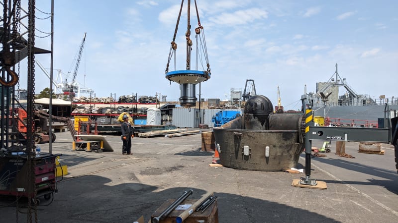
Pete, I really appreciate your inputs. IT is a new terminology for me so I'm digesting that one. This application is a steering bearing for a z-drive, it's located below the slewing gear. Speeds are low, forces are high, direction is varying. My gut is concerned about fatigue. If the bearing race has to flex to conform to the housing this could cause fatigue. This boat hit a rock and there has been substantial damage to everything in the drive. This is the shaft assembly:

PXL_20210812_193423740_v3jfkp.jpg
 
Tugboat - Those are pretty large clearances. Have you thought about possibly forcing shims into the larger gaps?
 
I have considered the idea of using a metal filled epoxy to set the bearing in. As a cylindrical roller bearing, the outer race does not need to be free in the axial direction. At this time I am inclined to run it as is but the shim idea is intriguing. I will have access to the bearing after installation. With your idea in mind I will use feeler gauges to measure for uneven support around the race.
 
> IT is a new terminology for me so I'm digesting that one.

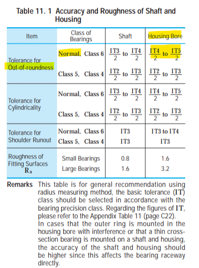
Yeah, me too. It's something I've been trying to figure out but not sure I've got it yet. I found another reference related to bearing housing roundness, this time from NSK which is a little different
Screenshot_2021-10-13_141443_zuiskq.gif


What is IT4/2 to IT5/2... well it's way narrower of a tolerance than SKF's IT7. For 730mm housing that's somewhere less than 36um/2 = 18um = 0.0007"

Why do we get such a lower roundness tolerance from NSK than SKF? Beats me, maybe I interpretted the SKF tolerance wrong. The NSK tolerance seems more straightforward to interpret for roundness since they specifically use the word roundness there. Although the NSK adds a confusion factor when they express the number as IT5/2 as if it's a 2-sided tolerance (so maybe max minus min can be up to 0.0014 instead of 0.0007?... beats me).

Along with roundness the NSK table mentions cylindricity... I don't know the difference other than I'd assume cylindricity is something like a 3D version of roundness... might flag problems with axial taper. That's something I'm going to try to figure out one of these days. You wouldn't think it would be so complicated to find an understandable roundness spec.

As far as your big-ass slow-ass bearing, I've never worked with anything like that, so have no idea. I agree with you fatigue from flexing of the outer ring seems like an important potential consequence of the out of round condition, especially if the load is varying or rotating. Two other miscellaneous thoughts on that:
[ul]
[li]1 - The note on the bottom of the NSK table above mentions that housing roundness is more critical when the fit is tight... which is the opposite of your situation, your looseness may make the out of round somewhat more tolerable.[/li]
[li]2 - They also mention thin cross section bearings are more vulnerable. While thinness is not quantified, CRB outer races/rings seem like thin cross section to me compared to deep groove bearings which seem a lot beefier.[/li]
[/ul]

=====================================
(2B)+(2B)' ?
 
I was reading in SKF literature that IT tolerances are radii and not diameters.

This is funny as the vendor kept giving me a dimension that resulted in clearance numbers that were double what they should be for the part. He argued that the clearance is on "both sides".
 
IT stands for International Tolerance Grades I believe.
They are fundamental tolerances and can be the basis for axial runout or any other dimension or feature.
I believe the classes are grouped more about what is commercially attainable, than what is technically required.
Sometimes the "tolerance" is the total to be applied to the nominal dimension, so 1/2 is disposed on each side of the dimension.
If the vendor is describing this kind of tolerance and dimension, and I understand the vendor's description correctly, he has it wrong.

The ISO sub-system of limits and fits for holes and shafts ( bearing bores and seats) are the more common H7, g6, etc.
That system of tolerances has the decency to be clear as to what is meant. +0.000 / -0.032 etc.
They are based more on what is technically required.
---------
It seems like most bearing manufacturers' literature talks about "radial" and "axial" internal clearance.
Most regrettably I believe you will find "radial" internal clearance is really total clearance in the "radial" direction. That is, diametral clearance.
See the attached image screen-shotted from the SKF website.
 
 https://files.engineering.com/getfile.aspx?folder=ae8d19a4-e6fd-4246-9a29-0faef74a2fd7&file=SKF_radial_clearance_is_really_diametral_.png
> I believe the classes are grouped more about what is commercially attainable, than what is technically required

Or a related thought, I think the tolerances mentioned above from SKF and NSK seem to be geared towards people manufacturing these parts, rather than towards users inspecting / maintaining the parts.

So what do you think is an appropriate roundness tolerance for users (inspecting used equipment)

In the absense of any guidance, one interpretation would be that every housing bore measurement taken only needs to individually falls within tolerance (example H6), but it doesn't matter how far the housing measurements differ from each other.

I just posted this question on another forum that you and I are on. Maybe Tom from SKF or one of the others will weigh in.


=====================================
(2B)+(2B)' ?
 
Pete said:
In the absense of any guidance, one interpretation would be that every housing bore measurement taken only needs to individually falls within tolerance (example H6), but it doesn't matter how far the housing measurements differ from each other

This is exactly what I am banking on. I picked H10 as my baseline diameter tolerance. This structure gets quite a bit of welding done on it after final machining so I have no idea if the deviations are from distortion due to welding or the impact itself. The unit has been in operation for 35k hours at this point.
 
Well... Tom came though on the other thread and posted some great information.

He directed me to the European SKF PUB BU/P1 17000/1 EN October 2018, which looks like it includes an updated version of the previously linked 2011 SKF Maintenance handbook in front, and product tables in the back (1100+ pages).

On pdf page 146/1152 (which is marked as page 144) is section B.6 Bearing interfaces Tolerances for bearing seats and
abutments.

This part looks relevant.

SKF said:
shaft seats to grade IT6 dimensional tolerances and grade IT5 total run-out tolerances
housing seats to grade IT7 dimensional tolerances and grade IT6 total run-out tolerances
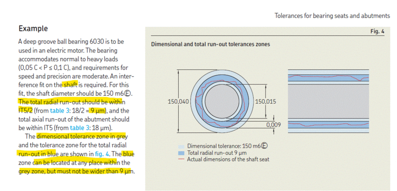
So we have two different terms "dimensional tolerance" and "runout tolerance". They clarify what these terms mean with an example on the next page. It shows the dimensional tolerance in grey and runout tolerance in blue. The blue runout tolerance tells us how close together the readings need to be to each other (and it's a narrower band than the gray dimensional tolerance). And they clarify the way we interpret IT5 for that runout tolerance IT5 (18 microns) is 9 microns per side so we'd be looking for the diamteral measurements to be within 18 microns of each other

The example is for a shaft fit of m6 which is the familiar type of fit table tolerance we deal with ....but they're also calling it dimensional tolerance... how are these two things m6 and IT6 related? I know in m6 the letter m is related to clearance/interference and the number 6 is the tolerance part but I'm not sure if that 6 is necessarily IT6. I'll think about that.

I'll try to clarify with him whether he thinks these tolerances are applicable for maintenance checks.
SKF_Example_wuahbn.gif


=====================================
(2B)+(2B)' ?
 
Thanks for posting the picture, I could not see it in the other forum.

With that information or appears my radial run out is not acceptable being equal to the total clearance allowance.
 
electricpete said:
The example is for a shaft fit of m6 which is the familiar type of fit table tolerance we deal with ....but they're also calling it dimensional tolerance... how are these two things m6 and IT6 related? I know in m6 the letter m is related to clearance/interference and the number 6 is the tolerance part but I'm not sure if that 6 is necessarily IT6. I'll think about that.

Ok, yes the 6 in m6 does seem to match IT6. Referencing the box figures at the top, the m tells us how far the bottom of the box is above 0 and the 6 tells us how tall the box is (tolerance). The box has a height of 40-15 = 25 microns.... which matches IT6 for "dimensional tolerance". And the graphic in the SKF example in the previous post is using 18 microns which matches IT5.... which is what they're citing for the shaft seat "runout tolerance"

tables_y4h8gz.gif


=====================================
(2B)+(2B)' ?
 
ok, one more update to preserve my newfound meager understanding of seat roundness requirements for posterity...

Tom from SKF clarified in the other thread "We like roundness specs to be 1 or 2 steps/classes tighter. So if k5 shaft fit roundness should be IT4(/2) or IT3(/2) for radial runout."

It seems to contradict the earlier part of the 2018 SKF document I quoted where they said
shaft seats to grade IT6 dimensional tolerances and grade IT5 total run-out tolerances
housing seats to grade IT7 dimensional tolerances and grade IT6 total run-out tolerances
but that earlier part didn't really make sense anywa, since the fit that we select includes a second number that can vary based on application requirements.

And indeed table 5 and table 8 in section B.6 of the 2018 SKF document show examples where the IT grade associated with the runout tolerance is always one less than the IT grade associated with the dimensional tolerance, just like Tom said.


=====================================
(2B)+(2B)' ?
 
My curiosity about the fit was whether roller skidding would occur - with heavy loads (always?) this is probably not going to be an issue.
 
Pete, I think your explanation has successfully made it through. If I call my housing IT10 and the out of roundness is IT9 then I'm good to go!


dvd, Outer race rotation is one of the two "normal" failure modes for ball and roller bearings. It shows up as pitting on the gear set as the alignment goes out of spec. It usually starts occuring around the 60k hour mark. Some manufacturers will notch the outer race for pins. I've seen others hammer pins into the oil holes (those ones usually break). Other manufacturers put the bearings in replaceable carriers. Tapered roller bearings tolerate interference fit on the cup race which eliminates the problem. With low speed bearings such as this one I don't expect skidding to be a problem. The bearing spends most of its life oscillating a few degrees and then rotated a few times a day.
 
> Pete, I think your explanation has successfully made it through. If I call my housing IT10 and the out of roundness is IT9 then I'm good to go!

That's good news. I posted all this at work yesterday (it's work related... just a few days before you posted I had to provide expedited feedback on a shaft out of round condition.... now I know that I partially missed the mark on that, but at least now I've learned enough to do better next time). I was planning to look up the IT9 and post your tolerances but my workday ended and you beat me to it. I'm glad you didn't end up making a bad call based on my earlier comments.

In retrospect, it makes good sense that the spec for roundness in um needs to be vary with the dimensional tolerance in um. IF (like my earlier incorrect interpretation of the SKF document) we declared IT6 was the runout tolerance for ALL housings, that would means 50 micron allowable variation in diametral measurements for your 730mm shaft regardless of the dimensional tolerance. That makes some sense if the dimensional tolerance is IT7 (80um range of allowable values). It probably wouldn't make any sense if the dimensional tolerance was IT10 which I think is up around 280um. It definitely wouldn't it make sense if the dimensional tolerance was IT3 which (if the table extended to that range) would be around 20um (how can the allowable variability among measurements be larger than the width of the allowable range of values....it can't!).

An interesting thing I observe about the IT tolerances... they disappear from the table at the large dimension low-tolerance area... indicating these options are never used. It seems consistent with the fact that bigger dimensions (like yours) tend to get a higher IT grade number. It looks like the IT grade table takes into account the dimension of the part (part size is one of two parameters we use to read a table value), but for some reason it doesn't take it into account enough to match modern practice, and so higher IT grades tend to be specified for larger parts

=====================================
(2B)+(2B)' ?
 
Sounds like you have it figured out. I've wondered about using bismuth in repairs:


I can't find much in the way of properties though. It's modulus and strength would be nice to know but since there doesn't seem to be much on the web I'm guessing it's not used for this type of repair.
 
Status
Not open for further replies.

Part and Inventory Search

Sponsor