Continue to Site

Eng-Tips is the largest engineering community on the Internet

Intelligent Work Forums for Engineering Professionals

  • Congratulations KootK on being selected by the Eng-Tips community for having the most helpful posts in the forums last week. Way to Go!

BEHAVIOR OF WELDED PLATE CONFIGURATION 1

Status
Not open for further replies.
Replies continue below

Recommended for you

I don't believe that is a very accurate model as it neglects the bending capacity of the two plates which are presumably both fixed at one end.
EDIT: that is not exactly what the initial sketch shows, but I am assuming that is what the OP meant.

BA
 
[blue](Kootk)[/blue]

My work doesn't speak to that. Rather, it simply demonstrates the logical necessity of there being some degree of composite behavior.

Understood.

[blue](BAretired)[/blue]

Shouldn't we have T = C = V*L/t where L is the length of cantilever and t is the thickness of one plate?

Not really. It's acting more like a moment frame.
 

WARose said:
Quote:
(BAretired)

Shouldn't we have T = C = V*L/t where L is the length of cantilever and t is the thickness of one plate?


Not really. It's acting more like a moment frame.

Precisely, but it was modeled as a shallow truss.

BA
 
BARetired said:
I don't believe that is a very accurate model as it neglects the bending capacity of the two plates which are presumably both fixed at one end.

As I mentioned to WARose, I hadn't intended the model to be accurate. Rather, I'd intended it to:

- Demonstrate that some degree of composite behavior will manifest itself.
- Serve as a conservative estimate of shear demand at the weld.
- Be simple.

My model "A" fully acknowledges the bending capacity and independent cantilever action which you've alluded to. However, without getting fancy, I've no way to quantify how much load goes to each path.

I like to debate structural engineering theory -- a lot. If I challenge you on something, know that I'm doing so because I respect your opinion enough to either change it or adopt it.
 
I suspect that there are additional secondary forces in this setup and to get a handle on these I would initially assume no weld @ the tip....this allows the two pls to deflect each carrying it's share of the load....now when we look @ the x-section of the deflected tip, we have two independent x-sections with each having it's own rotated x-section.....now what force would be required in each pl to result in a x-section of one rotated section when the weld @ the tip is present....I get an additional tension in the top pl and compression in the bottom pl both of which are eccentric to each pl....
 
Hello

If assume .5" x 2" plates that are each 6" long with 1000lbs at end of 6"length the Calc is
Inertia of two plates= .16 in>4
Q= A x Y centroid of each Pl=(2 x .5) x .25=.25in>3 (inches cubed)

q=(V x Q)/I= (1000x .25)/.166=1506lbs/in so total slip force between plate=1506 x 6=9036lbs

So aprox stress in 1/2 eff weld at end=9036/(.5 x 2" width)= 9036PSI

If 1" thick pl Fb (bend stress) at wall is:
(6" x 1000lbs) x .5/.166=18KSI. If two plates act as one. So stress at end is about 1/2 that at wall. This does not seem out of line for any still interested.

According to the code mentioned by Hotrod10 it does not take much metal or bolts over a given length to resist shear load. This allows a top plate and bottom pl to act as a beam instead of two seperate plates. This is strickly theoretical and not a recommendation to do this.
 
I found the horizontal shear force, Vh in the weld to be 3PL/8t where:
P is load on end of cantilever (P/2 on each plate)
L is length of cantilever
t is thickness of one plate

Using the example of TimSchrader2 above,

Vh = 3*1000*6/(8*0.5) = 4500#

Looks like one of us is out by a factor of 2.


BA
 
Hello BAretrired

I can see T=C= aproximatly PL/t= aproximatly Vh. If assumed as a truss (sort of) as mentioned above. I do not see where the 3/8 x T comes from. That would be a diff of 1/.375=2.66 to the PL/t using the truss assumption.

The method of shear flow does not ignore the moments in the beam at the wall. I used a example problem from "strength of materials" By E.P. Popov. about pg 170.

 
Hello TimSchrader2

I agree that Vh = PL/t when a truss is assumed, i.e. pinned joints. My current value of Vh = 3PL/8t considers the two plates fixed at one end instead of pinned, a different model. If anyone is interested, I could show the derivation.

BA
 
TimSchrader2

I checked my result with a different method and still arrive at Vh = 3PL/8t.

Just wondering...using your method:
q=(V x Q)/I= (1000x .25)/.166=1506lbs/in so total slip force between plate=1506 x 6=9036lbs (agreed)
So Vh = 1506 x 6/2 = 4518# at each end.

BA
 
For those who have been asking, here is the actual configuration of the steel in question. It doesn't really matter at this point because the project parameters changed and this isn't something we are looking at anymore, but I've been following this thread as the debate has been very interesting and I still want to know how this would behave.

getfile.aspx
 
Hello

BAretired. I conservatively neglected the weld at the wall and only applied the Vh to the weld at the end. Was not sure the weld at wall end resists this flow shear Vh between the plates as they bend. Since they are welded to the wall i assumed they are part of the fixity to the wall, and so the wall is doing the resisting not the weld. So, I assumed the conservative perspective.

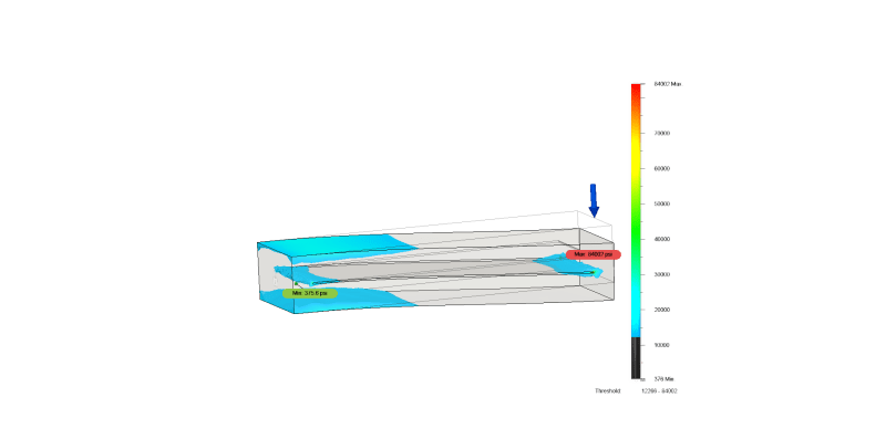
The below fusion 360 FEA (Quickly done) shows about 12-10 KSI (Von Misses) just next to the weld. But that could be a hot spot, this model would need more work to fully converge the solution. There is a .03" gap between the plates and 1/2" of metal connecting on each end to simulate the welds. I did use a full radius to minimize a singularity/hot spot at the slot edge. i expected to see more stress at the welds, this shows the higher stress just before the weld.

In any case, when in doubt I will use a a few plug welds with a doubler plate to get several plates to act as one, when they are much wider then the 2" I assumed. Which appears to be the actual case. i do not think the OP Ted needs a plug welds. Unless loads/stresses are real high

ENGTIP1a_v3_v1_yzbtci.png
 
Status
Not open for further replies.

Part and Inventory Search

Sponsor