greg2835,
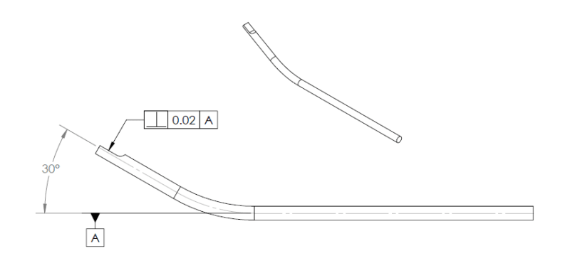
First off, you certainly wouldn't want to use perpendicularity since none of the features are, at the risk of stating the obvious, perpendicular. Angularity would be your control of choice - perpendicularity (and parallelism) are really just special cases/subsets of angularity, as far as I know there is little fundamental difference aside from the obvious fact that perpendicularity/parallelism should only be applied to features which are nominally perpendicular/parallel respectively to the primary datum reference. Regardless if the part is cylindrical or otherwise should not prevent you from applying an angularity control - you can define a datum axis from the cylindrical portion of interest and control angularity from there.
This brings me to my next point - you cannot derive a datum plane as shown, especially not applying the datum feature reference to a centerline - it must be applied to a physical feature. My recommendation would be to utilize a datum axis from the cylindrical portion of interest (horizontal in the view shown) - this datum axis is actually the intersection of two datum planes.
I think your main concern is going to be ensuring that the flat at 30deg is controlled to the same/similar angularity as the cylindrical portion bent to 30deg as well. I'm not sure how others feel about this but the first thing that pops into my mind is that you could reference a second datum feature B from the 30deg bent cylindrical portion* which would orient the 2x mutually perpendicular datum planes created by A and the angularity tolerance on the flat could be referenced to (A|B).

