3D,
While you bring up some valid points, I can't say I fully agree.
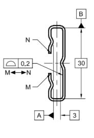
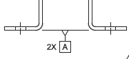
The examples you mention, such as figure 4-33 - the last one you described, detail applications of the datum feature symbol to irregular feature of size. The datum feature symbol is approriately associated with a dimension line of the 3 mm width basic dimension:
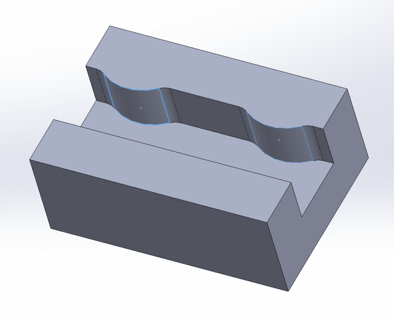
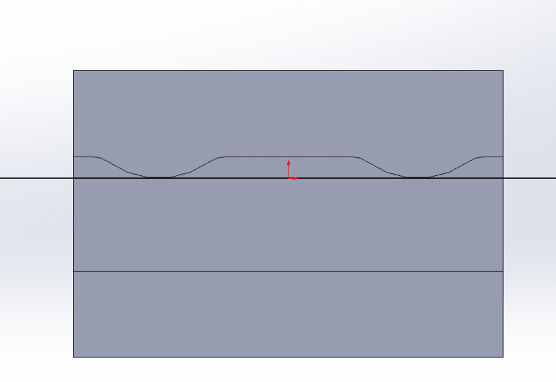
I have solid reasons to believe that in this and similar cases the intent is to indicate derivation of a center plane datum from the actual mating envelope of the irregular FOS; the AME would be two parallel planes at maximum separation, one contacting the 2 bumps and the other the one bump on the other side. So, the use is unique for that.
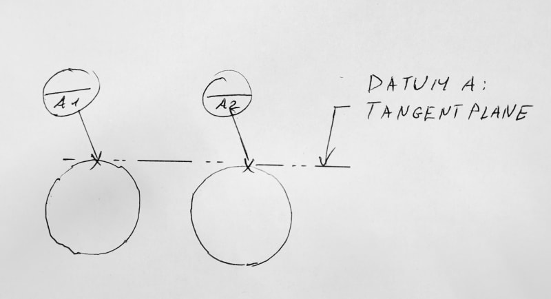
When the intended datum plane to be derived is a plane tangent to the surface, I would say that different conventions apply. For a non-size feature application, there is no dimension line to associate the datum feature symbol to, and we need to consider the 2 main methods to designate a datum feature on the drawing:
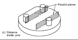
1. When a complete surface of the part is to be used for mating with a datum feature simulator, it's labeled by a datum feature symbol, attached to the surface or an extension line from it. This could also apply to 2 coplanar surfaces like in figure 7-52.
2. When the considered datum feature should only contact the datum feature simulator on local elements, datum targets of the appropriate contact type (points, lines, areas) should be used. If the contacts are defined by tangency to a plane, as in the OP's case, this can be indicated on the drawing by a phantom line passing through the datum targets, and possibly a matching note, if considered necessary.