Continue to Site

Eng-Tips is the largest engineering community on the Internet

Intelligent Work Forums for Engineering Professionals

  • Congratulations GregLocock on being selected by the Eng-Tips community for having the most helpful posts in the forums last week. Way to Go!

Bending moment, Shear force for a beam on a simply supported beam. 4

Status
Not open for further replies.

pike12

Structural
May 18, 2023
7
Hi,
From the problem in the image, how do we express P in terms of F? Does the couple generated by the I-beam on top of simply supported beam translate as-is into the bottom section and we can draw this as just another beam with 3 point loads? I am trying to refresh my Strength of Materials knowledge but don't know how to approach this.
Thank you, in advance.
 
 https://files.engineering.com/getfile.aspx?folder=8bc2182e-d03d-4957-ae45-e9e81e5f187f&file=SFD_BEAM1.PNG
Replies continue below

Recommended for you

In coordinate systems like the XY coordinate system, up is typically considered positive. What’s the rationale for the convention of up being negative in bending moment diagrams?
 
quote I am not sure where you found this convention, dik, but it is not intuitive.][/quote]

It was the international convention 55 years back when I first got into stress analysis. I no longer have a source and it may have changed. It is intuitive. With a right hand coord system, the forces could have any of the three axis directions. The face of the surface under consideration would take that axis. For example a force on the x face, acting in the x direction and the stress would be σxx and a force acting in the opposite direction would be -σxx (compression), in the same way, a force acting in the positive x face in the y direction would be -σxyor (tau)xy. Moments were taken the same way Mxy would be a moment on the x face with the vector in the y direction. Mxx would be a moment on the x face in the x direction (this would be torsion).

I dunno... seems pretty straightforward.

-----*****-----
So strange to see the singularity approaching while the entire planet is rapidly turning into a hellscape. -John Coates

-Dik
 

positive is the direction of the right hand orthogonal axis system, generally. +ve x is in the direction of the +ve x-axis. It could be up, down, sideways, or whatever.

-----*****-----
So strange to see the singularity approaching while the entire planet is rapidly turning into a hellscape. -John Coates

-Dik
 
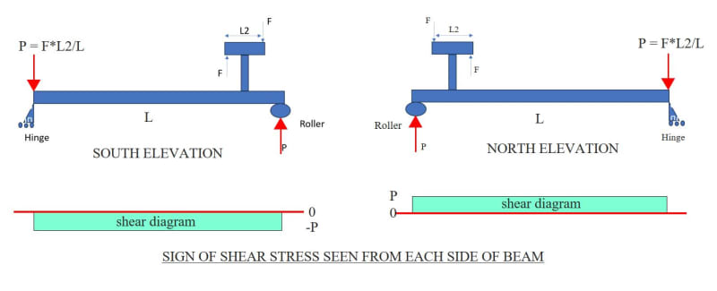
Shear stress as seen from each side of the beam (Y axis pointing upward). If the Y axis points downward, the sign of the shear stress is reversed.

Capture_l8y0si.jpg
 
I checked this with software. I divided the "a" portion of the beam into 3 equal segments, just to illustrate the increasing moment from Joint 1 to Joint 4 (where the frame is attached).

P = 5k
a = 16 ft
b = 4 ft
L = 6 ft (I changed symbol for L2 to simply "L")
HT = 10 ft (even though HT does not matter to the beam solution)

R1 = -1.5k
P = R2 = 1.5k

V = -1.5k throughout beam
M1 = 0.
M4L = -288. k-in [left side of Joint 4]
M4R = 72. k-in (right side of Joing 4)
M5 = 0.

It's a little difficult to do by hand because we are so practiced to draw shear and moment diagrams for the typical beam loads of concentrated forces and uniform loads. Adding the moment from the frame just makes our brains work a little harder.

To solve for P
Sum(M) = 0 = F(L/2)*2 - P(a+b)
P(a+b) = F*L2
P = F*L/(a+b) =5k*6'/(16'+4') = 30/20 = 1.5 k

 
NOLAscience &[COLOR=#EF2929 said:
BA[/color]]
P = 5k; should be F = 5k, right?
a = 16 ft
b = 4 ft
L = 6 ft (I changed symbol for L2 to simply "L".) L was already used for total span (a+b), but okay.
HT = 10 ft (even though HT does not matter to the beam solution) HT is height of Tee.


Status
Not open for further replies.

Part and Inventory Search

Sponsor