Continue to Site

Eng-Tips is the largest engineering community on the Internet

Intelligent Work Forums for Engineering Professionals

  • Congratulations SDETERS on being selected by the Eng-Tips community for having the most helpful posts in the forums last week. Way to Go!

Bending moment, Shear force for a beam on a simply supported beam. 4

Status
Not open for further replies.

pike12

Structural
May 18, 2023
7
Hi,
From the problem in the image, how do we express P in terms of F? Does the couple generated by the I-beam on top of simply supported beam translate as-is into the bottom section and we can draw this as just another beam with 3 point loads? I am trying to refresh my Strength of Materials knowledge but don't know how to approach this.
Thank you, in advance.
 
 https://files.engineering.com/getfile.aspx?folder=8bc2182e-d03d-4957-ae45-e9e81e5f187f&file=SFD_BEAM1.PNG
Replies continue below

Recommended for you

the applied F couple is reacted by a P couple. remove the Tee (the loaded structure above the beam), replace with a point moment F*L2 and the CL of the vertical leg.

A simply supported beam loaded by a moment ... reactions are a couple P*L = F*L2 ... yes? the BM diagram starts at zero at the LH end, increases linearly to the load point, drops by F*L2, then increases linearly to zero at the RH end

"Hoffen wir mal, dass alles gut geht !"
General Paulus, Nov 1942, outside Stalingrad after the launch of Operation Uranus.
 
You can put the F loads straight onto the main beam (or put the resultant moment straight onto the main beam) and the reaction P at the roller is the same either way.
 
P = F*L2/(a+b) or F*L2/L where L is span.
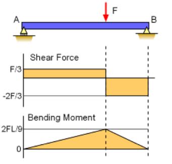
Sign of shear and moment shown below is the usual convention.

Capture_mjmyia.jpg
 
Shear diagram is correct... I'd use the opposite signs... +ve shear. +ve force on a +ve face, and a -ve force on a -ve face at the other end...

I use the international convention for signs... You often encounter SFD and BMD drawn using the opposite signage.


-----*****-----
So strange to see the singularity approaching while the entire planet is rapidly turning into a hellscape. -John Coates

-Dik
 
I don't think that shear diagram is correct.
The reaction at the left side and right side will be different, and there will be a step in the diagram "a" away from the left support.

I think the shear diagram is correct. When I typed my previous response I missed the upward force "F"
 
Net applied force on the system in the y-direction is 0, so the only reactions are resisting the moment. This case could be redrawn with a point moment at "a" from the left support. It doesn't matter where the point moment is on the beam - it will force the reactions to be equal and opposite. The V/M Diagrams drawn by BA are definitely correct.
 
Theres really no room for debate on this. The primary beam element is cut free from the 'T' element. The applied forces on the T cancel out resulting in only a concentrated moment being applied to the primary beam element.

There is no concentrated shear in the span of the beam, so there is no jump in the SFD.
 
Proof that engineers will argue about anything.
 
Other than the sign of his moment diagram, using international convention, his moment and shear diagrams are correct. Moment and shear diagrams are often drawn opposite to what international convention requires. The reaction on the LHS is down. This is a neg force on a neg face, ie +ve. As you move away from the support the moment increases linearly. The moment is positive (via RH rule). The resisting moment has to be -ve, else it accelerates, which is what the BMD shows... [pipe]

-----*****-----
So strange to see the singularity approaching while the entire planet is rapidly turning into a hellscape. -John Coates

-Dik
 
Another way of looking at it is to ignore the T shaped object constructed on the beam. The only load on the beam is a moment, and it could be 'anywhere'. The only reactions are to resist this moment being applied at the beam supports and these reactions are equal and opposite to resist the applied moment from the T shaped object.

-----*****-----
So strange to see the singularity approaching while the entire planet is rapidly turning into a hellscape. -John Coates

-Dik
 
The BM and SFD by BAretired make complete sense to me and so do your explanations. Thank you, everyone for your responses.
 
Capture_mmppqe.jpg
dik said:
Other than the sign of his moment diagram, using international convention, his moment and shear diagrams are correct.

A simple beam supporting gravity load has tension on the bottom and compression on the top. I consider that to be positive moment. For length 'a', this beam has compression on the bottom and tension on top, which I consider negative moment. The short section 'b' has positive moment.

If there is some international convention which says otherwise, I am not aware of it. Common practice is as I have indicated above.
 
As long as your rebar is on the right side of the beam - use whatever convention you want [2thumbsup]
 
My error... that should be shear, not moment...

"Shear diagram is correct... I'd use the opposite signs... +ve shear. +ve force on a +ve face,"

-----*****-----
So strange to see the singularity approaching while the entire planet is rapidly turning into a hellscape. -John Coates

-Dik
 
dik said:
My error... that should be shear, not moment...

"Shear diagram is correct... I'd use the opposite signs... +ve shear. +ve force on a +ve face,"

I am not sure where you found this convention, dik, but it is not intuitive. The sketch below indicates positive shear on the left end and negative shear on the right side of a beam loaded with gravity load F. When the reaction at A is upward, shear is positive, but in our case, the left reaction is downward, so shear is negative all the way across the beam.

Bending moment at any point 'x' in the span is the integral of the SF Diagram over length 'x', so it makes sense to call the shear negative for consistency, because we choose to call the moment negative for length 'a'.

Perhaps it's not worth debating, because if we view the beam from the opposite side, the sign of the shear is reversed. As Luceid suggested, if you know what you're doing, use whatever convention you like.
Capture_pdqqy3.jpg
 
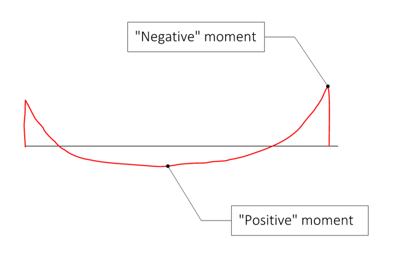
I think that people working in concrete would typically flip the "sign" of the moment diagram from your image above BA, as a tendency to get the moment diagram on the tension side - thus the diagram shows you which side of the beam the rebar is on. This isn't explicitly correct with the mathematical integration and whatnot - but practicality overrules for designers. I think almost all of the time I have seen concrete moment diagrams that look like this, where folks call the moment of the line "negative" and below the line "positive."

test_vvfccd.png


Again, whatever works for us!
 
I've seen that too, and normally there is no difficulty understanding what is meant. In the case at hand, a negative sign was used on both the SFD and BMD. But maybe it's time to put the question to rest.
 
Status
Not open for further replies.

Part and Inventory Search

Sponsor