Eng-Tips is the largest engineering community on the Internet

Intelligent Work Forums for Engineering Professionals

  • Congratulations waross on being selected by the Eng-Tips community for having the most helpful posts in the forums last week. Way to Go!

Bending stress and deflection on a beam with composite cross sections

Status
Not open for further replies.

blkfrd

Electrical
Jul 3, 2005
15
US
I am analyzing a system that can be modeled as a 2nd class fulcrum. The link below about 1/3 of the way down the page shows an example of a 2nd class fulcrum.

2nd class fulcrum Link

The part that makes up the beam is a composite part made up of a turnbuckle (see link below), threaded tube and a rod end/heim joint that have different cross sections. The beam has a turnbuckle where part of it is a solid male LH threaded rod and part of is a female RH threaded tube. The male portion of the turnbuckle threads into a different threaded tube and the female portion of the turnbuckle has a male threaded rod end/heim joint screwed into it.

Turnbuckle Link

I know the fulcrum arm length, load arm length load, load amount and the moment of inertia of each of the individual portions, but i'm not quite sure if I can calculate an overall moment of inertia of the beam to analyze the stress and deflection of the entire beam as a whole or if I need to determine the load/bending moment at each unique portion of the beam and analyze each section of the beam separately. Any help would be appreciated. Thanks


TC
Comm and GPS Systems Engineer
 
Replies continue below

Recommended for you

Tmoose: while I agree with your thoughts, this is the way A LOT of aftermarket suspension parts are built for all manner of cars.
 
Thanks for the replies! The turnbuckle has male and female threads so both ends do have jam nuts. Rod Ends are generally rated for axial loads as a percentage of the radial rating. For example, a rod end with 20,000 lbs. radial load rating has a axial load rating of 3000 lbs (15% of radial load rating).

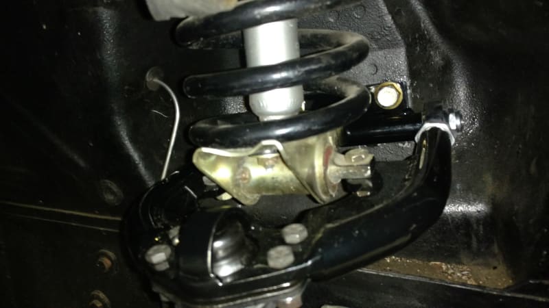
I can eliminate the turnbuckle and extend the tube length and just have the rod end threaded into the tube, but rod end adjustment is a PITA. You have to remove the upper control arm and partially disassemble it to adjust the rod ends. I have a set of prototype uppers on my test car (see pic) and they are built like that. Setting alignment requires a "guess" on how much to adjust rod ends for caster/camber before installing it, but if the alignment is not good, then you have to remove the upper and partially disassemble it (remove the spring tower mounting bracket between the 2 rod ends) before you can adjust the rod ends.

I'm trying to make the part as "user friendly" as possible so you can adjust it in-place. For me, having to remove the upper to adjust it is not a big deal because I understand suspensions and alignment, but I don't want my customers or their alignment shop to have to battle with the uppers to get them installed.

I'm considering making the upper completely tubular and non-adjustable and building in a positive caster offset and negative camber offset into the uppers and be done with it. As much as i'd like it to be in-place adjustable, I'm not convinced this would be the best approach. For coil over setups, the same upper is used without the spring perch mounts.

prototype_UCAs_installed_pwiwjs.jpg


TC
Comm and GPS Systems Engineer
 
OP recently said " Rod Ends are generally rated for axial loads as a percentage of the radial rating. For example, a rod end with 20,000 lbs. radial load rating has a axial load rating of 3000 lbs (15% of radial load rating)."

I believe the axial rating is based on the way the ball is retained in the socket, and the reduced contact area.
If we assume the threaded stud is good for the bending induced by that load too, at least statically, where does that put your design at maximum spring compression ? (Note this is an improper assumption, based on OEM literature mentioned below.)

Where is the bump stop located?
I'd still expect the jam nuts to loosen pretty quick, and for fatigue cracks to start appearing in the threads after hitting several thousand bumps. If the only thread is on the rod end, with no convenient but weakening turnbuckle, the alignment of the rod end orientation is enforced, and I'd grind the threads off in a gentle arc inline with the tie rod housing, so a uniform surface would be subjected to highest stress from bending loads. That would probably mess up the evil bending load transfer over under and thru the threads, bringing on jam nut loosening and thread fretting even sooner.

Page 28 here discusses rod end "strength."

My interpretation -
1 - the static radial strength is for pure tension because they use the thread root diameter.
2 - they state that static axial loading " does not take into consideration bending of the shank due to a moment of force. "
 
Tmoose said:
2 - they state that static axial loading " does not take into consideration bending of the shank due to a moment of force. "

Yes- the axial load refers to the axis of the fastener passing through the eye of the bearing; in practical terms this is how much load it takes to press the ball out of its seat. The technical guides from every rod end manufacturer that I have personally used all spec their parts this way, and all bear the same disclaimer about rod ends in bending. It's on the user to develop case-by-case load limits for bending scenarios.
 
Thanks again for the replies. Here are some things to ponder...

If I build the uppers with the turnbuckle gone and the tube extended longer and just have the rod end at the end of the tube, a high strength tube insert will be used for a 5/8-18 high strength 4130 rod end. The rod ends have a radial strength rating of almost 18000 lbs and an axial load rating of 3600 lbs (I know i'm not specifying bending load rating). The location of the rod end threaded section will be almost at the end of the beam so the load on the threaded section will be almost the same as the reaction force at the end of the beam (at rod end bore centerline).

The installed load of the spring is about 1600 lbs (upper has a mech advantage of 1.7 so with 950 lbs of force at the ball joint due to weight on the tire, the spring load is about 1600 lbs). The spring rate is 420 lbs per inch and there will be about 2 inches of additional travel before coming into contact with the suspension bumper so the spring load will be about 2500 lbs max statically. The reaction force at the rod end bore centerline will be about 515 lbs (2 rod ends share 1030 lbs of reaction force). There will be more force dynamically due to shock loads and acceleration of the upper and spring caused by bumps in the road.

Up until a year ago, I had modified stock uppers that incorporated rod ends into them for several years. When I removed them to put the tubular uppers on, the rod ends were still in excellent shape and the female threaded tube that accepted the rod end was also in excellent shape.

The amount of thread engagement is very important and I specify the maximum amount of exposed threads when adjusting the rod ends on other parts to ensure adequate thread engagement. In this case, it will be about an inch.

TC
Comm and GPS Systems Engineer
 
OP said "I had modified stock uppers that incorporated rod ends into them for several years."

Do you have pictures of those modified stock control arms.
 
I don't. I actually threw them away about a year ago. They were essentially stock upper control arms that I had cut the end off where it mounts to the shock Tower and weld it some threaded tube to accept the rod ends. I did the same thing to the lower control arms also. The car had limited adjustability and I could not get the caster and camber numbers that I wanted on the car with the stock suspension parts so I made them adjustable.

I replaced all of that stuff with parts that I make for my business including the Prototype upper control arms about a year ago.

By the way the jam nuts have never come loose on the old Hardware or the new hardware

TC
Comm and GPS Systems Engineer
 
Status
Not open for further replies.

Part and Inventory Search

Sponsor

Back
Top