Continue to Site

Eng-Tips is the largest engineering community on the Internet

Intelligent Work Forums for Engineering Professionals

  • Congratulations KootK on being selected by the Eng-Tips community for having the most helpful posts in the forums last week. Way to Go!

bending torsion instability of steel pipe 4

Status
Not open for further replies.

robyengIT

Mechanical
Dec 20, 2013
894
Eurocode says that a steel pipe item (part of a structure) is not affected by a bending+torsion instability (i.e. when the torsion stiffness is bigger than the bending stiffness ??). I am looking of literature discussing and explaining such a statement. Thanks
 
Replies continue below

Recommended for you

if something perturbs the equilibrium and makes the section deflect in[b said:
x[/b] direction,]

In z-dir, I guess? (x - axial, y - vertical, z - out of xy plane)
 
Retired13,

I used this:
X orizontal
Y vertical
Z axial

So, I was correct, in that point I talked about x.

Indeed, the moment Mx (which I talked about in my example) is a flexural moment in the x direction, wich generate a deflection in y.
 
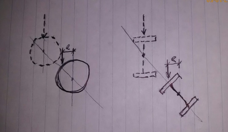
Which one below will be kicked into higher energy state after the additional T = P*e?

IMG_20200114_171856993_p0ct0v.jpg
 
IDS said:
This might be of interest:

this is a different type of buckling... this is buckling of the wall...like Cylinder buckling
other story
 
That's the LTB phenomenon graphically (not exact) explained. Yes, the pipe, n Now you can think a mathematical explanation for it. I am running out of bullets, please help yourself.
 
Omg, I understand that a I section is subjected to LTB and, in general, not a pipe. Thank you for the pictures. I asked for a mathematical analysis, starting from the equations of a beam and searching a condition where the total potential energy is maximum (if it is possible to find that condition, if it is not possible I'd like a mathematical explanation for that). If I asked for it, maybe I can't find it alone.
 
Billie93 said:
...if it is not possible I'd like a mathematical explanation for that

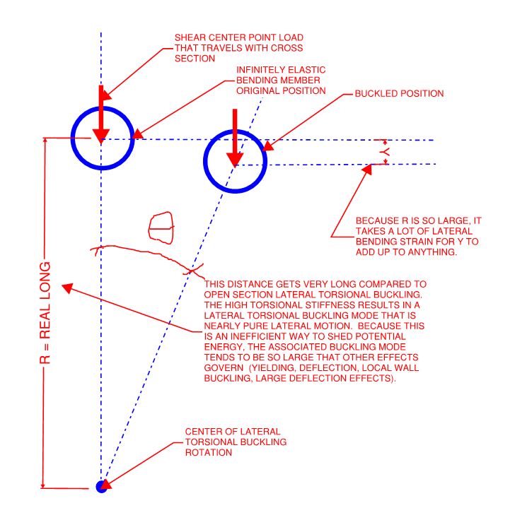
In my opinion, you'll not find such a mathematical explanation because it is in fact possible to laterally torsionally buckle an infinitely elastic, shear center loaded circular hollow section. See the mechanism below which is similar to retired13's work. When we say that these members cannot laterally torsionally buckle, what we really mean is that their lateral torsional buckling resistance is so high that it's of no practical interest to us as designers because other failure modes will kick in long before lateral torsional buckling becomes an issue. To numerically assess the lateral torsional buckling strength of a circular hollow section, I believe that one would use the usual equation for elastic lateral torsional buckling as follows:

1) Use the relatively large St. Venant torsional stiffness value associated with your closed section and;

2) Eliminate the term representing the torsional stiffness associated with cross sectional warping.

c01_tfucdc.jpg
 
Thank you for the answer KootK, I agree with every thing you said. Obviously, having big torsional and flexural rigidity, the LTB does not happen for pipe. As I said before, I want to study the problem of particular structures where there are very long pipe (effective length of 50m or more) and I wanted to understand if in these case LTB could happen.
I agree that the right formulation is the "famous" one that we use for open section: to find out that formula I think that the hipotesys of open section is used only to define the warping function, but pipes doesn't warp, so the formula should be' valid.
 
Billie93 said:
Thank you for the answer KootK, I agree with every thing you said

Well I like the sound of that. And you're most welcome.

Billie93 said:
As I said before, I want to study the problem of particular structures where there are very long pipe (effective length of 50m or more) and I wanted to understand if in these case LTB could happen.

It's an interesting problem. I have the following thoughts to offer;

1) As span increases with, say, a point loaded member:

- vertical stiffness decreases with L^4.
- lateral stiffness decreases with L^4
- torsional stiffness decreases with L^1
- bending stress increases with L^2

2) For a member for which deflection is being meaningfully controlled, I don't ever see LTB overtaking deflection.

3) At some rather long length, I suspect that LTB does in fact overtake bending. And I think that Retrograde's interesting table above reflects this fact, even if not for an [ry = rx] member per se.

4) For any real world tube of such great length, it will likely be prudent to consider the destabilizing effect of loading above the shear center rather than at the shear center. There really are not many common ways to load a tube through the shear center and loads located at other locations may well result in:

a) Pure torsional buckling if it is the case that the tube would stay put and the load source would translate laterally or;

b) Something like constrained axis lateral torsional buckling if it is the case that the load would stay put and the tube were free to translate laterally.

 
Where is the destabilizing force in that diagram though? Effectively, I think all buckling needs to have some kind of force reducing the stability of the member (think secondary moments in euler buckling, or the compression flange of a beam wanting to continue to rotate after an initial rotation, or the top chord of a truss "pushing" through to the tension chord). I just can't rationalize that there is any force there that is causing the buckling. In fact in that sketch I think all the forces are pulling the member back to its centerline.
 
Billie93,

I don't know why I keep coming back here. Anyway, here is some math you might be interested in, Link. And here is another one, Link
 
canwest said:
I think all buckling needs to have some kind of force reducing the stability of the member (think secondary moments in euler buckling, or the compression flange of a beam wanting to continue to rotate after an initial rotation, or the top chord of a truss "pushing" through to the tension chord).

In the real world, yes. However, it's usually a geometric imperfection rather than a force per se. And there's no reason to think that our tube wouldn't have such a geometric imperfection. Member sweep would do the trick. In a more abstract way, so might residual weld stresses at the seam welds.

In the world of mathematical, bifurcation bucklin, such a perturbing force / imperfection is not required. Moreover, if the perturbation were a force rather than an imperfection, it would be mathematically incapable of influencing the result. Eigenvalue analyses are largely agnostic to perturbation forces. When we do the classic Euler column derivation in university, that is independent of any perturbation. Rather, you're simply seeking the compression load at which flexural stiffness drops to zero.

canwesteng said:
Where is the destabilizing force in that diagram though?

canwesteng said:
I just can't rationalize that there is any force there that is causing the buckling.

Think of it more as a force acting through a destabilizing motion rather than a destabilizing force alone. In my sketch, [theta] rotation produces the vertical displacement [Y} which brings the load closer to the ground and, therefore, reduces the potential energy of the system. This is the sense in which LTB is destabilizing.

canwesteng said:
In fact in that sketch I think all the forces are pulling the member back to its centerline.

I show one external force in my sketch and, considered in the context of the [theta] motion, it is clearly destabilizing.

As for internal forces, yes, they to tend to pull the member back to it's centerline. That, in effect, is the member's LTB resistance. And it's also true of the strains generated in, say, a wide flange beam when it embarks upon an LTB excursion.
 
DrZ said:
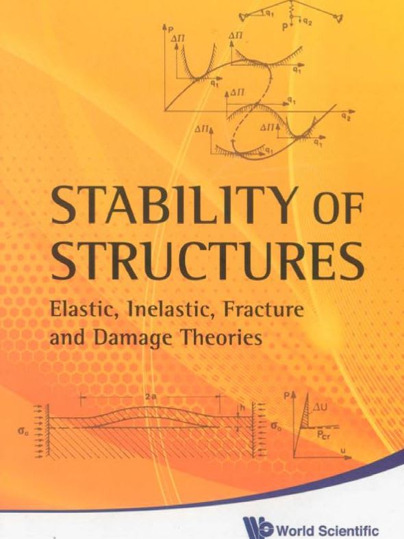
If you are really into the subject of buckling/bifurcation, this book goes into it to a dizzying extent. I bought the hardback at the last AISC conference. It's quite dry but very informative.

Another great option for getting so deep into the weeds that you're staring up at lillipads is shown below. It's lively and engaging in spades, however, as first principle stuff tends to be.

c01_ezcjry.jpg
 
If we ditch the world of mathematics in favor of the real world, there is a significant stabilizing effect to be considered with slender tubes. The applied load acting through the sag present in a slender tube will, itself, create a restoring action serving to inhibit lateral motion. This represents our leaving small deflection theory in the dust however. For this reason, among others, real world LTB truly is the domain of members which are stiff in the loaded direction and relatively soft, in comparison, with respect to lateral motion and twist.
 
Ok, ignore the my use of the word force, but ultimately there needs to be second order effects that destabilize the member for it to continue to buckle. I don't see how there are any of those in the pipe. Your force brings the pipe closer to ground, but won't move the pipe laterally or torsionally, whereas if it were an open section, the compression flange is going to continue to rotate, just like a column continues to buckle. In your sketch, the external force isn't destabilizing, it only wants to push the member straight down.
 
canwesteng said:
..whereas if it were an open section, the compression flange is going to continue to rotate, just like a column continues to buckle.

It is a subtle but important mistake to think of lateral torsional buckling soley in terms of the compression flange acting like a column. A salient example is the case of unrestrained cantilevers being most effectively braced at the tension flange.

Alternately, simply think of the portion of the tube cross section experiencing compression stress as akin to a compression flange. Such is the case with higher aspect ratio rectangular tube sections which can LTB, right?

canwesteng said:
Your force brings the pipe closer to ground, but won't move the pipe laterally or torsionally

Bifurcation buckling is not about actually moving anything. It's about applied load reaching a point where resistance to a hypothetical perturbation would vanish. An Euler column never actually buckles. It simply reaches a level of applied load at which its resistance to buckling drops to zero. Of course, for design purposes, neutral stability is little better than instability.

canwesteng said:
In your sketch, the external force isn't destabilizing, it only wants to push the member straight down.

The same is true of the applied load on a wide flange when LTB is derived for that situation.
 
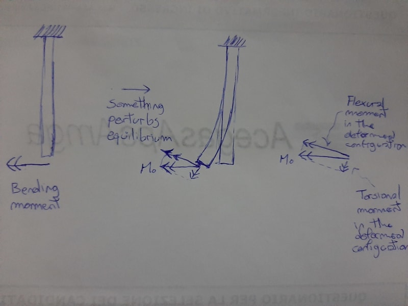
20200116_212948_ejir7v.jpg

Here is the destabilizing force, in my opinion. If the pipe deflect, a torsional moment appear. As we do when we talk about stability, we can see that torsional moment as a loss of torsional stiffness. If M0 is big enough, the torsional stiffness of the pipe becomes 0 and we have instability.
Of course, the torsional stiffness of a pipe is very big, so M0 has to be very big to have torsional instability. As we said, we have different kind of collapse before reaching a critical torsional point, and that is sure.
Am I wrong?
Of course, if we increase the span, we reach the critical point with a smaller value of M0.
I started this discussion (in an italian forum, to be honest) beacause I'm a curious man and because I want to understand the behavior of very long pipes subjected to axial compressive force and bending moment: maybe I discover that the resistance of the pipe is a little smaller in the combined M,N buckling verification.
 
Status
Not open for further replies.

Part and Inventory Search

Sponsor