Continue to Site

Eng-Tips is the largest engineering community on the Internet

Intelligent Work Forums for Engineering Professionals

  • Congratulations KootK on being selected by the Eng-Tips community for having the most helpful posts in the forums last week. Way to Go!

Best steel column-beam-brace joint to the column weak axis (web direction) ?? 2

Status
Not open for further replies.

Abdelrahman_Yousef

Structural
Jan 19, 2019
9
As the subjects suggests , this joint has been giving me headaches.
In the direction of the column main axis, I have a moment connected main beam and I need the back transverse stiffeners in the column.
How do I connect the strut and brace in the other direction while maintaining erect-ability of course .

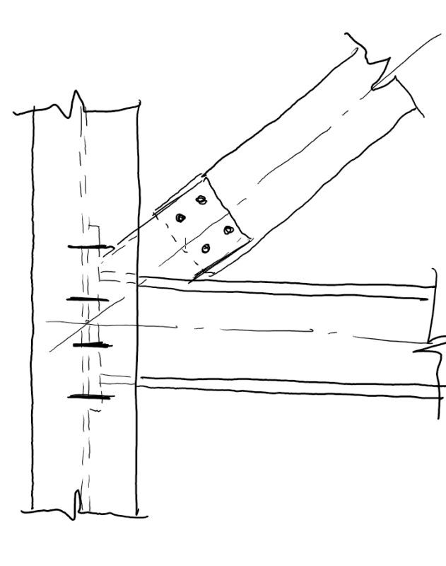
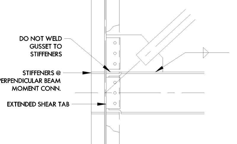
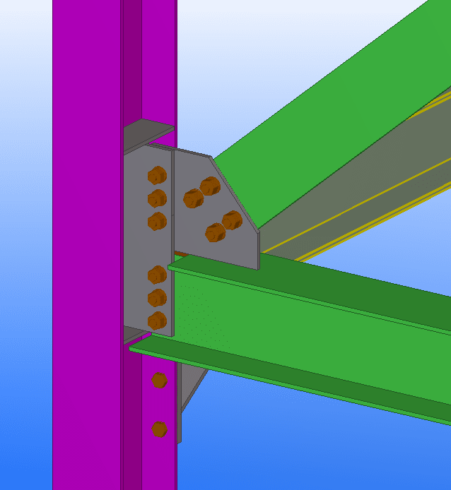
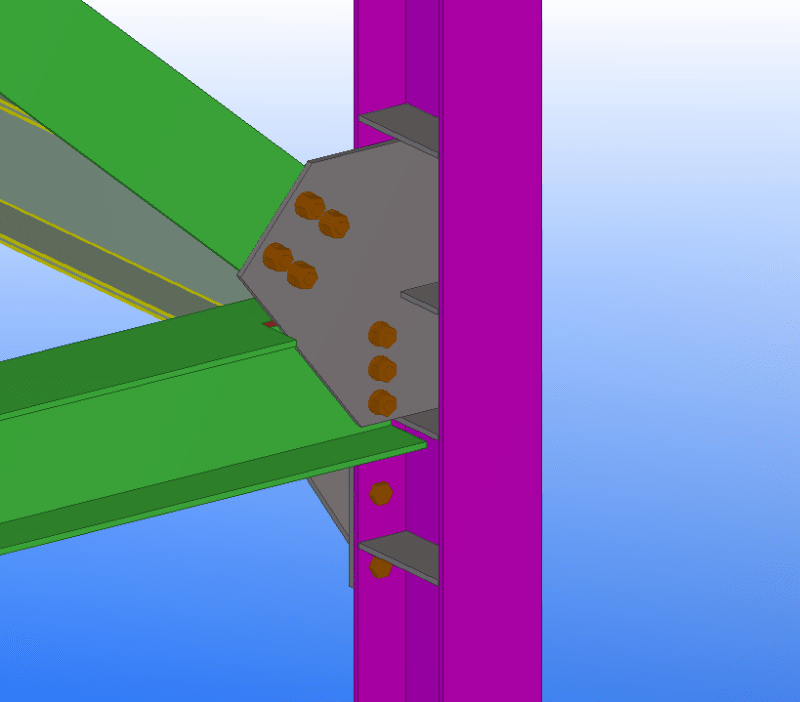
I've seen the following 2 samples connections before, so can anyone give me advantages and disadvantages of each ?
what checks may be critical that might pass me by ?
or if there are any other suggested shapes.
1111_rttvhl.png


2222_hvgixi.png
 
Replies continue below

Recommended for you

These are tricky connections. My experience has always been with a connection similar to the second one you posted. The single "extended shear tab" that connects to the web and brace is better than the rectangular "shear tab" and additional gusset for the brace. The first option has some additional eccentricity, fabrication, and load path issues that are better handled by the (preferred) second option. I've seen the second option but with a straight down cut instead of the profile cut. That was the preference of our shop since the nesting of the profiled plates created just as much waste.

Here are some things to think about:
A. Confirm the load case (ie. which member is in tension/compression) you are checking. This will affect the resultant force.
B. Check whether the force distribution based on the bolts handling the rotation or the rotation at the stiffeners.
C. What's the brace doing at the other end? You can save the field team some problems if you keep an eye on that.
D. Generally the checks are the same as for a shear tab: member end connection, bolt resistance, plate strength, plate stability, stiffener strength, weld strength, column strength and stability.
E. The main issue with these connections was always geometry driven. The eccentricities are small (width of a web, perhaps) but can add up.

Good luck.
 

1) I don't like the first one. Way too much eccentricity and plate bending.

2) The second one might be simplified by eliminating the second stiffener from the bottom. I don't think that you need that stiffener because your incoming strong axis beam will be delivering its moments through the haunch flange.

3) Given the option, I'd shift the brace work point such that the entire brace connection is to the beam and only the beam. This impacts the beam design, of course, but that's usually minor in my experience relative to the benefit to the connection. If you're a fabricator and not the EOR, you likely won't have this option.
 
Thank you for your answers.
Is there any design guide for the second connection ?

Furthermore, if I take the connection further inside the column web to avoid eccentricity , would it be impossible to erect or just little more difficult ?
 
The bolts have to be in a place where someone can get a wrench and tighten them. Pushing the bolts inside the flange is going to make erecting difficult. The exception would be if you had a fairly deep column, but you'll need to access the clearance on a case-by-case basis.
 
I'm kind of partial to connecting directly to the web if there are no obstructions. I'm not quite sure what you brace is (a flat plate?), but cope the edge of the flanges until it fits.
Annotation_2019-10-13_115455_nwptbx.png

It can be a bit more of a hassle for erection,but with the right people on site its not an issue. Lifting up several floors as a frame between column splices is quite do-able on site in most cases.
 
Kookt said:
Given the option, I'd shift the brace work point such that the entire brace connection is to the beam and only the beam. This impacts the beam design, of course, but that's usually minor in my experience relative to the benefit to the connection. If you're a fabricator and not the EOR, you likely won't have this option.
Thats my thoughts though I've often encountered engineerers who try hard to avoid bracing to beam connections and much prefer the column. I can't understand why in most cases as unless there is a concern of insufficient shear capacity on the beam this often is easier and simpler all round.

Agent666 said:
I'm kind of partial to connecting directly to the web if there are no obstructions.
Why? (Curiousity and the desire to learn here.)

My immediate reation to the detail you posted is more difficult to fabricate, more difficult to errect and potentiall introducing unwanted moment into the column.
 
Why don't you end up with faceplate which welded on column flanges and use end plate connection which advised by @Agent666..

Thanks in advance!!
 
Here's my stab at the connection. This seems pretty easy to fabricate:

brace_conn_eso1xi.png
 
bhiggins, depending on what the connection looks like on the opposite end of the beam, that might be very difficult to erect - the horizontal stiffeners and the shear tab create a pocket that the end of the beam has to fit in to, which means the beam has to be brought in fairly straight on.

I like Agent666's detail, and use that style of connection often. But with the horizontal stiffeners in the column, I don't think it will work. Option 2 is definitely the better option in the OP. It's going to be ugly no matter what.

 
Human909, main reason I like it if it works (as others have noted may not in this situation) is that the eccentricity is virtually zero, so for a little hassle in the erection you all but do away with all the secondary eccentricity moments present in the other details. The end plate doesn't usually need to be thick because its only delivering a vertical shear to the web. Theres no (or its very small) horizontal loads going into the web. So in the right situations this can help quite a bit in keeping your column sizes down a weight or size due to no moment like you get in many of the other connections where you might be resolving force distribution created by implementing uniform force method or similar means.
 
I design this type of connection from time to time. An extended shear tab give your erector flexibility and is "easily" fabricated. Based on the number of bolts you're using, your steel members look very light. If the column web has trouble taking the UFM force, add a doubler plate. The good thing about steel is it's reliable and you can stiffen the column to accommodate many types of connections.
 
 https://files.engineering.com/getfile.aspx?folder=5019adb5-a2bf-4564-b331-0c5ae3e15e3d&file=combined_pl_brace.pdf
Is IDEA STATICA reliable when analyzing all of these connections ? because manual calculations will take really long time
 
I have no idea about that computer program, but the calculation's are relatively simple. I use the modified uniform force method provided in AISC Engineering Journal, 1st quarter, 2008 (free for members), but the standard UFM also works fine.


Add the UFM forces to the beam's reaction forces, then design the extended plate for total shear and axial. The extended shear plate will be designed for the combined shear values of the beam + gusset and maximum axial from either (minimal due to beam-to-column-web conx.). That's my strategy. Best of luck to you.
 
human909 said:
Thats my thoughts though I've often encountered engineerers who try hard to avoid bracing to beam connections and much prefer the column. I can't understand why in most cases as unless there is a concern of insufficient shear capacity on the beam this often is easier and simpler all round.

You didn't ask a question here but I'm going to pretend that you asked "KootK, why do engineers go to such lengths to avoid connection eccentricity?". You know, because I'm interested in this and because I very much like the sound of my own voice:

I'm glad that you asked. I believe that eccentricity aversion is some combination of the following factors:

1) A genuine but misguided attempt to improve material efficiency. Yes, your members will always be lighter with no eccentricities. And, if it were only about the members, that argument would hold water. However, as any fabricator will tell you, connections factor in big time. So making big ugly connections at the expense of minimum weigh members is often a flawed approach with respect to installed cost.

2) Ignorance. Truly, some folks just don't have a grip on the nuances.

3) Convention. Keep on doing what we've been doing.

4) EOR laziness born of the division of labor between EOR and fabricator when it's delegated connection design. EOR work goes nice and fast with no meaningful consideration of the connection design which will get passed off to the fabricator to deal with. So why not keep things as simple as possible on the EOR side and go concentric?

5) EOR perception of design office efficiency. This argument was more convincing 50 years ago when automated design was unavailable and accommodating eccentric member designs was a production office nightmare. It's not nearly such a big deal nowadays with modern design software in play.

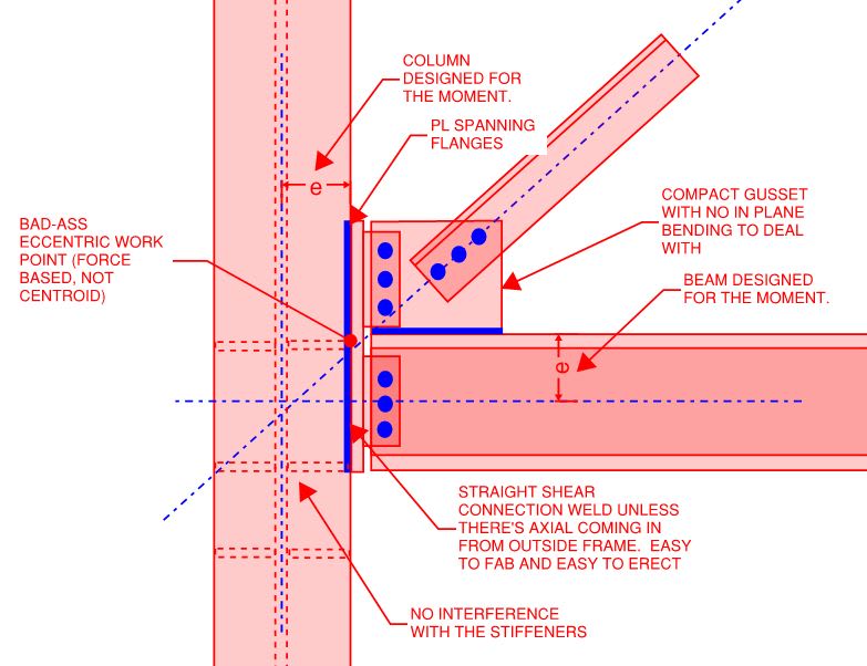
Doesn't this look easy to fabricate and erect? I obviously don't know the scale of the member size impact here so that's something that would need to be evaluated on a case by case basis.

Another, subtler argument that I'd make against a strict adherence to eccentricity elimination is that, based on the varying stiffenesses of the connection elements, I tend to be pretty skeptical that eccentricities are really eliminated to the extent that we tell ourselves they are. Especially when bolt are involved with their inherent slip. I almost consider 1/2 member depth to be a reasonable, minimum eccentricity for the member design regardless of the connection detailing.

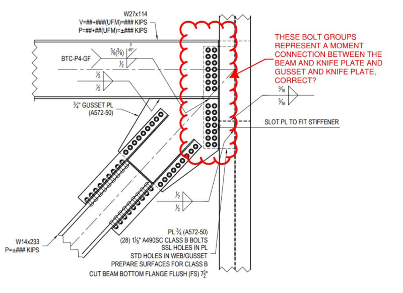
c01_dbr5pf.jpg
 
Meh. I'm not a huge fan for that connection above. Why?
1. You're blocking in a portion of the column. So your erection sequence has to be dialed in if there are bolted connections coming in to the flanges. How else would you place those bolts?
2. You're blocking in a portion of the column. So now you'll have to provide some sort of drainage hole in your stiffeners. Sure. It's just a drilled hole, but if you have 200 of these on a project, then you need to have 200 stiffeners carried over to the drill line (adding another timing step and potential for QC/QA) or you're now subdividing that piece mark into "avec drilled hole" or "sans drilled hole" [EDIT: Also fire rating for that blocked portion]
3. You're blocking in a portion of the column. So your plate spanning across the flanges will get (potentially) a one-sided weld on the outside. This would be best if it's a shop weld, but because of the placement, it might be a costly field weld.

I don't like blocking in a portion of the column because you lose access. If things in the field deviate, I'm not sure which connection I would like to "fix" but it probably wouldn't be the one with blocked access. It's a great design concept for force transfer, though. And if your PM and shop QC can really identify the scale vs. cost for this (versus less "multiple piece connection") I think you could challenge convention and go for it.

I do like the straight cut gusset for the brace, though. And I do like your thoughts #1 through #5. Spot on. Mandatory fabricator experience for everyone.
 
KootK,

I like it. However, provided the brace goes into tension, the weld connection your cover plate to the flanges will see some axial.

It's still pretty straightforward, with just a little bit of force accounting to do. But certainly much easier than a full-blown UFM.
 
As a matter of curiosity, I also had a question with respect to Dr.ZW's excellent detail.

c02_zytsee.jpg
 
skeletron said:
1. You're blocking in a portion of the column. So your erection sequence has to be dialed in if there are bolted connections coming in to the flanges. How else would you place those bolts?

- Blind bolts.
- Do haunch on the top as with the bottom so there's no interference (not sure if there's a floor here).
- Switch to a beam stub connection for the moment frame connection.
- Switch to flange plates welded to the column for the moment frame connection.

skeletron said:
2. You're blocking in a portion of the column. So now you'll have to provide some sort of drainage hole in your stiffeners. Sure. It's just a drilled hole, but if you have 200 of these on a project, then you need to have 200 stiffeners carried over to the drill line (adding another timing step and potential for QC/QA) or you're now subdividing that piece mark into "avec drilled hole" or "sans drilled hole". [EDIT: Also fire rating for that blocked portion]

- fab the vertical plate as two separate plates, one for the beam and one for the gusset. provide a 1/2" gap between the bottom of each plate on the low stiffener behind it. Drainage. No holes, no carrying anything to the drill line.

- I wasn't aware of the fire rating issue, can you elaborate? I do similar things often where 1/2 of an HSS is used as a stiffener in a wide flange beam.

skeletron said:
3. You're blocking in a portion of the column. So your plate spanning across the flanges will get (potentially) a one-sided weld on the outside. This would be best if it's a shop weld, but because of the placement, it might be a costly field weld.

- What's the problem with a one sided fillet weld? Are you seeing some kind of bending in the fillet weld issue? As I'd mentions, this was for a condition without significant transfer of axial from beam to column.

- Partial pen if it makes us feel better. Not that the prep is free.

skeletron said:
If things in the field deviate, I'm not sure which connection I would like to "fix" but it probably wouldn't be the one with blocked access.

I don't see it. Can you provide a specific example where you feel this would be a concern? On the brace side, you've got this nice vertical face to mess with, only shear connections, and repair as you see fit. Easy. On the moment side, what... a flange stiffener will be mislocated vertically or something? Seems like a reach. I could maybe see in the field weld inspection being an issue if that's a thing.


winelandv said:
However, provided the brace goes into tension, the weld connection your cover plate to the flanges will see some axial.

Whaaat? I don't see it and had specifically meant to avoid that. Can you elaborate? Are you thinking of moment in the plate as a result of the eccentricity between the vertical bolt lines and the plate?
 
Status
Not open for further replies.

Part and Inventory Search

Sponsor