Continue to Site

Eng-Tips is the largest engineering community on the Internet

Intelligent Work Forums for Engineering Professionals

  • Congratulations KootK on being selected by the Eng-Tips community for having the most helpful posts in the forums last week. Way to Go!

Best way to connect reference point to points subjected to vertical load

Status
Not open for further replies.

rte4563

Mechanical
Sep 28, 2022
40
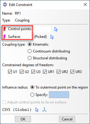
I have 3 points which will be subjected to 100 N. I want to connect them all to a reference point and simply put the 100 N on the reference point and not have to manually load the 3 separate points with the load. I tried constraint type coupling between reference point and three points as you see below. However, my model job aborts when I do it this way, if I for example try "tie" the model runs but im not sure I get the desired effect. How could I solve this problem? Is coupling the best solution?
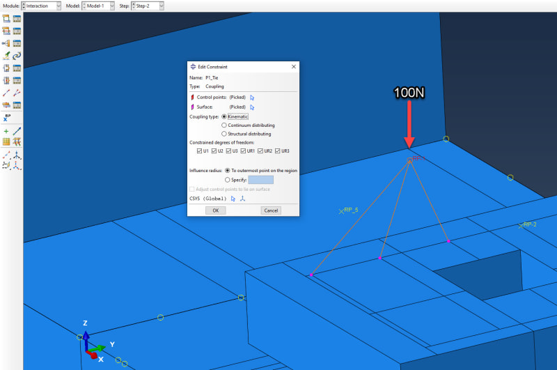
1_gs0t0i.jpg
 
Replies continue below

Recommended for you

I would use rigid body constraint for this purpose.
 
Cant I simply do coupling type Kinematic, condstrain all DOF's and get this rigid body behavior? Should I choose the reference point or the 3 nodes below as the "Control points" and "Surface"?

1_qhcle6.jpg
 
No, coupling constraints work differently and are meant for other purposes. They can be utilized to apply loads without making selected faces completely rigid. But rigid body constraint should work here.
 
I am still not sure I understand why coupling constraint wont work, althought its concrete its not supposed to be completely rigid, its supposed to be able to bend for example. The load is supposed to be applied at the reference point (there is some machinery on top of the foundation not modelled), but experienced by the concrete foundation on those 3 nodes with the same magnitude on each of them.
 
Check the descriptions of those constraints in the documentation. If you are applying the load only to points, their rigidity shouldn’t be a problem.
 
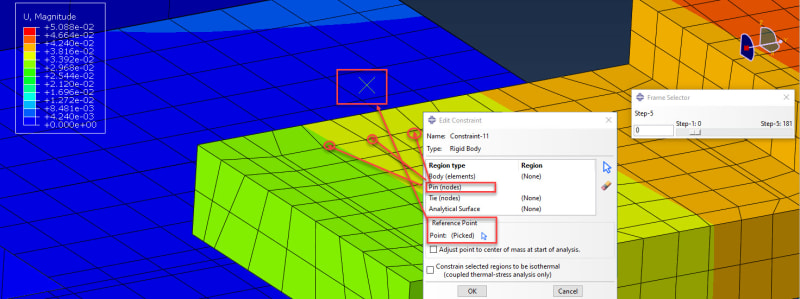
Does this look sort of right? I chose reference point as reference point, and region type as Pin (nodes).

1_bkahrc.jpg


Edit: Maybe it would have better to use Tie (nodes)to tie rotational and translational DOF's.
 
Right, I would use tied nodes too. Apart from that, it should be fine.
 
Another problem now if you dont mind[dazed] in the first picture I showed one reference point and 3 nodes. In reality I have about 7-8 reference points and all of them are connected to the same 15 nodes. I get the error message for the nodes: "INSTANCE XXX HAS TWO RIGID BODY REFERENCE NODES 2 (ASSEMBLY) AND 1 (ASSEMBLY). A NODE MAY BE ASSOCIATED WITH ONLY ONE RIGID BODY"
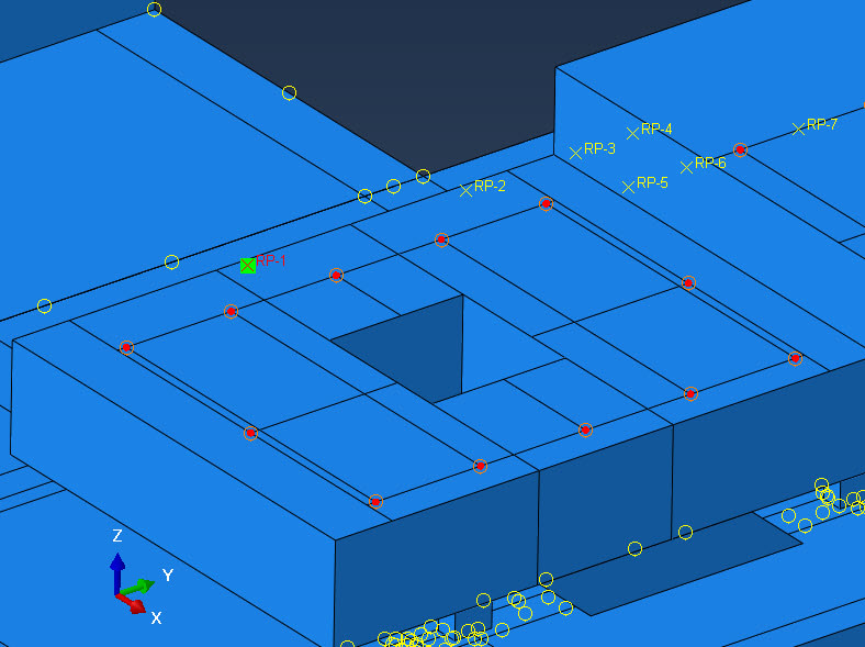
When I went back and tried coupling with kinematic constraint I get problems with overconstraint. Any other suggestions on what I could try? Abaqus does not seem to like these "hard locks". When I choose coupling type "structural distributing" it runs fine.

1_ayllep.jpg
 
Just make sure that each rigid body definition has separate nodes assigned and it should work. Nodes can't be shared by different rigid body constraint definitions.
 
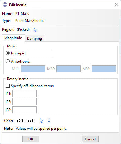
I apply inertia to these reference points (100kg, 200kg etc). Is there a way for me to check the final amount of kg applied to the model? I wanna check if the applied mass (kg) is the same amount of kg that comes out in the results, as a control to see if it has been applied correctly or not. Similar to how you would check if you apply 100kN you could check if the reaction force is total of 100kN in the supports.

1_d89lnl.jpg
 
You can use Query --> Mass properties for this purpose. It accounts for point masses.
 
Status
Not open for further replies.

Part and Inventory Search

Sponsor