Continue to Site

Eng-Tips is the largest engineering community on the Internet

Intelligent Work Forums for Engineering Professionals

  • Congratulations waross on being selected by the Eng-Tips community for having the most helpful posts in the forums last week. Way to Go!

Bi-axial bending chart - concrete column 18

Pretty Girl

Structural
Nov 22, 2022
93
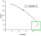
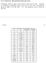
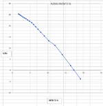
This is from "Reinforced concrete design to eurocodes" by prab bhat, page 371 and 372.
It has mentioned the it's for My/ (hb^2) = 2.

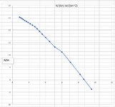
But I don't know how to reproduce with that ratio kept constant. So, I tried to create it with making the alpha and beta values at a constant ratio of 0.8 (beta = 0.8 alpha). Then I produced a chart.

Since I didn't reproduce the exact chart in the book, now I have another problem. I have got no reference chart to compare my chart with. Can anyone kindly help me find out if my chart is correct for the column dimensions and data I provided.

Are there any free software/ excel sheet to enter the column details mentioned below and compare it with my chart?

I'm concerned that my chart may not be correct as I don't see the part the book's chart have I have shown in the green rectangle below, when I produce my chart. I understand it cannot be the same chart, but if my chart is correct that "nose" like curve should also be in my chart isn't it.

1. Chart from the book
1734934729980.png
Untitled 5.jpg


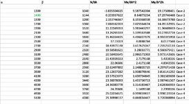
2. The chart I produced

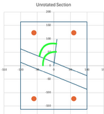
This is a rectangular column, h = 2000 mm, b = 1000 mm. I maintained "beta/ alpha ratio = 0.8".
4 reinforcement bars, 1 bar each corner. Steel percentage 4% (So, 1% bh area for each bar).
40 mm distance from column surface to the centroid of r/f for each bar.
fck = 30 MPa, fcd = 20 MPa, fyk = 500 MPa, fyd = 434.7 MPa.
Screenshot 2024-12-23 at 5.14.55 pm.png

Screenshot 2024-12-23 at 5.14.33 pm.png
Screenshot 2024-12-23 at 5.14.21 pm.png
 
Last edited:
Replies continue below

Recommended for you

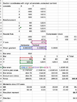
Further to my previous post, I have reviewed the calculation method in my spreadsheet, which is:
For a section with a defined NA angle:
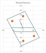
1: Rotate the section about the uncracked centroid, so the NA is horizontal and find the coordinates of all the reinforcement in the new orientation.
2: Find the strain gradient to the point with maximum compressive strain, perpendicular to the NA.
3: Find the strain and stress at each bar, with a stress cut-off of fy/1.15.
4: For bars in compression deduct the concrete stress (f'c/1.5).
5. Calculate the forces and moments about axes through the uncracked centroid, parallel and perpendicular to the NA.
6. Find the magnitude and direction of the resultant moment, which in general will not be perpendicular to the NA.
7. Convert to moments about the original axes.

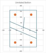
I have attached a spreadsheet with this calculation (macro-free!) and also a calculation using the un-rotated section, which gives identical results for the resultant magnitude and direction.

biax6-1.jpgbiax6-2.jpg
 

Attachments

  • Biax reo example.xlsx
    25.1 KB · Views: 10
Further to my previous post, I have reviewed the calculation method in my spreadsheet, which is:
For a section with a defined NA angle:
1: Rotate the section about the uncracked centroid, so the NA is horizontal and find the coordinates of all the reinforcement in the new orientation.
2: Find the strain gradient to the point with maximum compressive strain, perpendicular to the NA.
3: Find the strain and stress at each bar, with a stress cut-off of fy/1.15.
4: For bars in compression deduct the concrete stress (f'c/1.5).
5. Calculate the forces and moments about axes through the uncracked centroid, parallel and perpendicular to the NA.
6. Find the magnitude and direction of the resultant moment, which in general will not be perpendicular to the NA.
7. Convert to moments about the original axes.

I have attached a spreadsheet with this calculation (macro-free!) and also a calculation using the un-rotated section, which gives identical results for the resultant magnitude and direction.

View attachment 3015View attachment 3016

@IDS
Many thanks for providing this file and for your response.
I'm still going through this. I will have more questions to ask though :)
 
Further to my previous post, I have reviewed the calculation method in my spreadsheet, which is:
For a section with a defined NA angle:
1: Rotate the section about the uncracked centroid, so the NA is horizontal and find the coordinates of all the reinforcement in the new orientation.
2: Find the strain gradient to the point with maximum compressive strain, perpendicular to the NA.
3: Find the strain and stress at each bar, with a stress cut-off of fy/1.15.
4: For bars in compression deduct the concrete stress (f'c/1.5).
5. Calculate the forces and moments about axes through the uncracked centroid, parallel and perpendicular to the NA.
6. Find the magnitude and direction of the resultant moment, which in general will not be perpendicular to the NA.
7. Convert to moments about the original axes.

I have attached a spreadsheet with this calculation (macro-free!) and also a calculation using the un-rotated section, which gives identical results for the resultant magnitude and direction.

View attachment 3015View attachment 3016

@IDS

Hi, I went through this. Many thanks for the detailed calculation spreadsheet. It helped me a lot to understand what's actually happening.

So, when you calculate the moments, the distances to the r/f were always measured by fixing the axes at the mid section (centroid of the section).
So the distances to r/f did never change, although we move the NA along the section (that resulted in varied stress of steel). Then we multiplied the "stress * area * fixed distances" to get the moment.

Further, I noticed you added "reduction of the concrete stress" as well from the tensile steel stress. Which I didn't think that I needed it before, now understand it's important.

Previously I was thinking that we need to make the r/f distances also vary as the NA moves (for moment calculations). Now I get that, for the moment calculations, we always should calculate the distances from a fixed point, like centroid.

However, my head still can't fully wrap around that fact as my brain always says opposite, "since NA moves, the distances to r/f should also vary when calculating moments" (Although everywhere I see I'm wrong, it's so counter-intuitive to my brain).

By the way, is this calculation sufficient to design the column for real life (safe) situations? So by this method, we can build the total 3d interaction surface as well as I see. Is that correct or is there any other considerations or fine-tuning of calculation needed? (I mean I know I didn't add the concrete forces yet, but this method is safe isn't it?)

Usually the Eurocode have a maximum column breadth to width ratio of 3 times the width of breadth (as I remember). Let's say there's some code allows 4 times the breadth. So, even with that code limit this method of calculation is valid, isn't it? because it's basic analysis applicable to any width? or is there any known limits for this method?

My next task is to combine the concrete forces myself and I'll see if it turns out ok. Fingers crossed.
Hi Pretty Girl, in reply to your post above:

Another way to do the calculation, which might be more intuitive, is to take moments about the NA, then add the moment due to the net axial force x distance NA to centroid. This will give exactly the same results. It follows that for a section with zero axial load you can take moments about wherever you like.

Yes, adjusting for the area of concrete displaced by the reinforcement can be significant, especially when there is a high proportion of reinforcement.

The basics of the method are exactly the same as for single axis design, and yes, the results are suitable for final design. One potential inaccuracy is that the rectangular stress block is an approximation based on a rectangular section. Where the section in compression is triangular the rectangular stress block is unconservative. Eurocode 2 has a reduction factor to allow for this, or use a parabolic-rectangular stress block for a more accurate result (although that makes the concrete force and moment calculations more complicated).

The code restrictions on column shape should be applied. The calculation is theoretically correct for any shape where the moment is applied uniformly across the full width, but that may not be the case for actual structures, so any shape outside the applicable code limits would require further investigation.

Hope to see your concrete results shortly. :)

Thank you for the response.

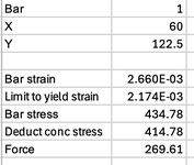
In your spreadsheet, I noticed you reduced the concrete stress from the compression steel (bar1). But shouldn't we only need to reduce concrete stress from the tensile bars?
 

Attachments

  • Screenshot 2025-01-11 at 1.51.25 am.png
    Screenshot 2025-01-11 at 1.51.25 am.png
    22.8 KB · Views: 3
work-notes-jpeg-2025-01-06-14_24_57-png.3074
 
Celt83's diagram provides the answer, but in words:

We calculate the concrete force based on the full area of the concrete, but there is no concrete at the bar locations, so the additional compression force provided by the reinforcement is: (Steel stress - concrete stress) x bar area.

The concrete is ignored in the tension zone, so there is no need to adjust the bar tension forces.
 
@Celt83 and @IDS

Thank you for the response.

We need to reduce it because we initially consider the full concrete area without reducing steel area, isn't it?
So, that means, if we initially reduce the steel area from concrete area, we don't have to reduce the concrete stress from steel stress, do we?.

example,
Ac, reduced = Ac - As
and Nc = Ac, reduced * fc

and now we don't have to reduce concrete stress from compressive area, and we can do it straight away like this?

Ns = As * fs

Is this also accurate because we initially reduced the steel area from concrete area? This should render the same output, shouldn't it? Or is there any unavoidable reason to deduct the concrete stress from steel?

or is your method (reducing the concrete stress later when calculating steel forces and moments) is more accurate than reducing it initially from concrete?

I see the centroid of the concrete compression area can move slightly (making concrete lever arm to over estimate a bit) if we reduce the steel area initially. As I see it will over estimate the concrete moments. I guess your method is more accurate in that manner?
 
Last edited:
@Celt83 and @IDS

Thank you for the response.

We need to reduce it because we initially consider the full concrete area without reducing steel area, isn't it?
So, that means, if we initially reduce the steel area from concrete area, we don't have to reduce the concrete stress from steel stress, do we?.

example,
Ac, reduced = Ac - As
and Nc = Ac, reduced * fc

and now we don't have to reduce concrete stress from compressive area, and we can do it straight away like this?

Ns = As * fs

Is this also accurate because we initially reduced the steel area from concrete area? This should render the same output, shouldn't it? Or is there any unavoidable reason to deduct the concrete stress from steel?

or is your method (reducing the concrete stress later when calculating steel forces and moments) is more accurate than reducing it initially from concrete?

I see the centroid of the concrete compression area can move slightly (making concrete lever arm to over estimate a bit) if we reduce the steel area initially. As I see it will over estimate the concrete moments. I guess your method is more accurate in that manner?
Yes, reducing the steel stress and reducing the concrete area are effectively the same thing for force, and will give exactly the same answer for a rectangular stress block.

The difference is in the bending moment, and reducing the steel stress for bars in compression will give a more accurate estimate of the centroid of the force, and the total moment due to the compressive force.

@IDS

Thank you.

Further you mentioned, that when calculating concrete stress, "where the section in compression is triangular the rectangular stress block is unconservative. Eurocode 2 has a reduction factor to allow for this, or use a parabolic-rectangular stress block for a more accurate result (although that makes the concrete force and moment calculations more complicated)."

So, I went through the Eurocode and found the following clause. I believe you're referring to this? If so, it says 0.8 as reduction factor, that's essentially the same reduction factor I used for rectangular compression area. As I used 0.8x (where x being the NA to compression fibre distance). So, if I follow the Eurocode factor, then there's nothing more I need to do as it's already reduced to 0.8x?

For the stress, I initially thought, since it's a triangular area, we need to divide fcd by 2 (Fcd/2), but then I noticed, the eurocode says "if the width of the compression zone decreases in the direction of the extreme compression fibre, the value "η fcd" should be reduced by 10%. I guess this is referring to triangular compression area we're having? so upto 50 MPa "η fcd" value that should be 0.9 * 1 * fcd, further reducing the stress towards the safety. So, that means if we use "0.9", we don't have to divide the fcd by 2?


Screenshot 2025-01-11 at 10.46.59 pm.png
 
Last edited:
@IDS

Thank you.

Further you mentioned, that when calculating concrete stress, "where the section in compression is triangular the rectangular stress block is unconservative. Eurocode 2 has a reduction factor to allow for this, or use a parabolic-rectangular stress block for a more accurate result (although that makes the concrete force and moment calculations more complicated)."

So, I went through the Eurocode and found the following clause. I believe you're referring to this? If so, it says 0.8 as reduction factor, that's essentially the same reduction factor I used for rectangular compression area. As I used 0.8x (where x being the NA to compression fibre distance). So, if I follow the Eurocode factor, then there's nothing more I need to do as it's already reduced to 0.8x?

For the stress, I initially thought, since it's a triangular area, we need to divide fcd by 2 (Fcd/2), but then I noticed, the eurocode says "if the width of the compression zone decreases in the direction of the extreme compression fibre, the value "η fcd" should be reduced by 10%. I guess this is referring to triangular compression area we're having? so upto 50 MPa "η fcd" value that should be 0.9 * 1 * fcd, further reducing the stress towards the safety. So, that means if we use "0.9", we don't have to divide the fcd by 2?


View attachment 3374
The lambda factor (0.8) is to account for the effect of replacing a varying, parabolic-linear, stress distribution with a uniform stress. It is based on a rectangular section but it is applicable to any shape.

I was talking about the additional 10% reduction in your 3rd paragraph. This additional reduction is because the average stress due to a parabolic-linear distribution applied to a triangle (with zero stress at the base) is reduced, because the wider part of the shape has the varying stress, and the area with uniform stress is reduced.

The design uniform stress (0.9*1.0*cd in this case) should be applied to the area of the triangular compression zone (allowing for the lambda factor). Why would you divide it by 2?
 
@IDS

Hi, thank you for the response.

In your excel spreadsheet, isn't your labels are swapped incorrectly? I mean the direction relative to NA should not be 111.15, it should be 84.59 and vice-versa shouldn't it?

Screenshot 2025-01-20 at 4.10.57 pm.png
 
@IDS

Hi, thank you for the response.

In your excel spreadsheet, isn't your labels are swapped incorrectly? I mean the direction relative to NA should not be 111.15, it should be 84.59 and vice-versa shouldn't it?

View attachment 3687
No, look at the plot of the unrotated section. The direction of the resultant moment relative to the X axis is less than 90 degrees, and relative to the NA it is more than 90 degrees.
 
No, look at the plot of the unrotated section. The direction of the resultant moment relative to the X axis is less than 90 degrees, and relative to the NA it is more than 90 degrees.

@IDS

Isn't it measured clockwise? Not like this? I believe you meant it's measured anti-clock wise?

Screenshot 2025-01-21 at 5.41.05 pm.png

Further, I realised that when the tensile steel reinforcement reaches it's max strain, since the concrete can't bear that much of strain in tension (and since we consider it's almost zero tension bearability), the concrete must have already cracked at that time isn't it. So in real life, inside of all the columns the concrete in the tension zone have physical microscopic cracks? so concrete in tension zone have physical microscopic gaps (due to cracks) that closes and opens in microscopic level when loads vary?
I mean not the concrete cracks because of other reasons, cracks because of this steel strain.
 
@IDS

Isn't it measured clockwise? Not like this? I believe you meant it's measured anti-clock wise?

View attachment 3742

Further, I realised that when the tensile steel reinforcement reaches it's max strain, since the concrete can't bear that much of strain in tension (and since we consider it's almost zero tension bearability), the concrete must have already cracked at that time isn't it. So in real life, inside of all the columns the concrete in the tension zone have physical microscopic cracks? so concrete in tension zone have physical microscopic gaps (due to cracks) that closes and opens in microscopic level when loads vary?
I mean not the concrete cracks because of other reasons, cracks because of this steel strain.
The direction of the resultant is measured as the anti-clockwise rotation from the X-axis, but it doesn't really matter as long as your angles are always consistent.

In a column with the NA near the centroid of the section there will be significant cracks in the concrete at the ultimate moment, and the capacity design assumes there is a crack at the section being checked, so the tension in the concrete is ignored. In between the cracks, yes there is transfer of stress between the steel and the concrete, and this causes microcracking in the concrete. This doesn't have a significant effect on the section bending capacity, but at working loads it does have a significant effect on deflections, which changes over time due to creep and shrinkage. But that's another story :).

@IDS Thank you for the response.

In your excel spreadsheet, you have calculated the strain as following,

((0.0035/500) * 60) + ((0.0035/250) * (122.5 + 37.5)

However, I'm confused why you used only "60" (bar distance from y axis) to get strain contribution on x axis, while you used "122.5 +37.5" which is a sum up of two components "bar distance from x axis + distance to strain zero from x axis" for y axis contribution. Why double standard?

Screenshot 2025-01-26 at 5.47.40 pm.png
 
@IDS Thank you for the response.

In your excel spreadsheet, you have calculated the strain as following,

((0.0035/500) * 60) + ((0.0035/250) * (122.5 + 37.5)

However, I'm confused why you used only "60" (bar distance from y axis) to get strain contribution on x axis, while you used "122.5 +37.5" which is a sum up of two components "bar distance from x axis + distance to strain zero from x axis" for y axis contribution. Why double standard?

View attachment 3989
Because we are working from the point where the NA crosses the Y axis, and using the strain gradients along the Y axis ("vertical"), and perpendicular to the Y axis ("horizontal"), so we use the distance from the point of zero strain to the bar in the "horizontal" and "vertical" directions. It's not a double standard.
 
Because we are working from the point where the NA crosses the Y axis, and using the strain gradients along the Y axis ("vertical"), and perpendicular to the Y axis ("horizontal"), so we use the distance from the point of zero strain to the bar in the "horizontal" and "vertical" directions. It's not a double standard.

@IDS
Thank you for the response.
Now everything seems ok for steel.

Now I'm gonna build 3d interaction surface (at this moment only for steel, later I'll combine concrete). For that, I'm gonna vary the neutral axis angle and distance and get N and M data. Then, should I use axial force (N) as y axis (vertical) and for resultant moment (M), for the x axis of the chart? and as the angle should I use the angle of direction relative to x axis to build the 3d interaction chart?
That's how I would do it :)
 
That's how I would do it :)

However, the direction angle relative to x doesn't go all the way to 0-90 degrees. So there must be something else. Some other angle. Maybe neutral axis angle, as the angle?

I'm asking this because I want to build something looks like below. I don't necessarily need 360 degrees, but at-least 0-90 degrees.

Screenshot 2025-02-01 at 7.54.44 pm.png
 

Part and Inventory Search

Sponsor