Eng-Tips is the largest engineering community on the Internet

Intelligent Work Forums for Engineering Professionals

  • Congratulations waross on being selected by the Tek-Tips community for having the most helpful posts in the forums last week. Way to Go!

Blind hole notch in shaft subjected to rotating bending fatigue load

Status
Not open for further replies.

Mihe

Mechanical
Aug 13, 2019
11
0
0
SE
Hi,
Is it a good idea to drill a hole in a shaft subjected to rotating bending fatigue load? Just kidding. However transverse holes in shaft (radially drilled holes) exist and need to be assessed in view of fatigue strength.
My question is about blind holes. Hence holes with a limited depth. Through holes can be assessed by FEA or formulas e.g. according to DIN 743. But what about blind holes.

See the figure.
Picture1_ghzk3j.png


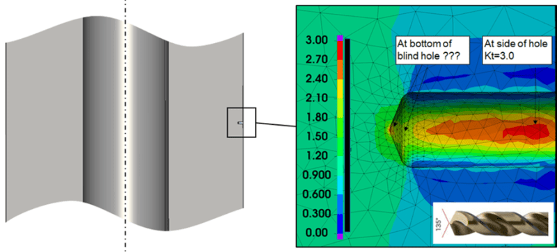
Given the geometry of the drill for the hole there are sharp corners at the bottom of a blind hole. In the figure the sharp corners at the bottom of the hole are modelled with a 1mm radius. In reality the corners are sharp or nearly sharp. If modelled sharp the FEA the stress results would of course be singular. This makes the blind hole more difficult to evaluate at least with stress based assessment.

Questions:
-What method could be used to evaluate the fatigue strength of such a notch at the bottom of a blind hole?
-Alternatively – are there perhaps references that say that the side of the hole (see figure) is the worst position and not the notches at the bottom of the hole? I have found one[1] but it is for aluminum and for very small holes and may not be relevant for larger holes in a steel shaft. In my case a 1/4" (6.35mm) hole.
-Or are blind holes worse that through holes?
Your inputs to this are very welcome
.
BR/Micke


[1] Geometrical size effect in the fatigue life predictions of aluminum wires with micro holes using methods of the critical distance, Engineering Fracture Mechanics, Volume 209, 15 March 2019, Pages 147-161
 
Replies continue below

Recommended for you

Speaking in terms of just raw magnitude, I don't see how it could be that much higher in a blind hole far from a edge than (say) a notch that takes up the entire side. (For which there is a lot of info available.) In fact, I would think it [the whole side notch] would be higher. The fact you are getting a k of about 3 shows it is probably in line with a table solution (for a full side notch).
 
Thank you for your inputs but the problem is not how to evaluate the strength at the side (Where Kt=3.0). The problem is how to evaluate the bottom of the hole at the sharp notches for which no stress concentration factor can be calculated.
BR/Micke
 
The problem is how to evaluate the bottom of the hole at the sharp notches for which no stress concentration factor can be calculated.

If you can't smooth it than why not use a table solution for a (full side) V-notch in a plate? That gives the max. stress [K] anywhere in the area. It's not realistic to have a perfect "tip" at the top of the notch in the first place. Most of those formulas have variables that consider the radius at that point.
 
Interesting question.

The deeper the hole, the further the tip of the hole from the area of maximum stress, leaving the limiting factor of the hole itself at Kt 3 remaining. So, if I had to take a wild guess, I'd probably expect that a very shallow hole might be the worst case scenario with a factor approaching that of a V-notch. As it gets deeper, I'd guess that the limiting stress case (not worst Kt value necessary) will gradually approach the Kt 3 limit based on the hole side.

I think WARose's suggestion for the V-notch is not entirely crazy for shallow holes. Probably a wee bit conservative in the case of a deep hole which might have the tip at the centre of the section.

Also, if I were to guess without doing an analysis or checking some table, I'd estimate that a through hole will be roughly the same as a blind hole that has significant depth (maybe 1/4 - 1/3 shaft diameter or greater?).
 
I think WARose's suggestion for the V-notch is not entirely crazy for shallow holes. Probably a wee bit conservative in the case of a deep hole which might have the tip at the centre of the section.

True.....and thanks for pointing that out. (That's something I forgot to say.) I think it's conservative....but not accurate.
 
Interesting one. I would be curious to know what radius at the tip of the drill bit would get you to Kt = 3? With the 1 mm radius you have already, your Kt looks to be about 2.5 or thereabouts, so probably not far off.

I suppose that in practice a real drill bit will have its tip worn down to a smooth point, even if its a few microns' radius. But then I imagine your Kt is going to be >> 3.
 
@WARose - from a practical front, if you assumed it to be a conservative approach (I suppose a bit of checking should be done to verify that but it passes the pub test), you could then increase the depth of the hole until it's sufficiently deep such that the estimated tip stress is inconsequential to the design intent. Always seems strange to take more material out to achieve a 'stronger' design.
 
Thank you all for your inputs. This is a great forum.

The suggested approach with a V-notch may be a way forward. Some further concerns:
-First, as I understand, it will require a radius to be set at the sharp corners. In DIN 743 (“Calculation of load capacity of shafts and axles”) a circumferential V-notch case exist that could be referenced. The nose angle is there 60 degrees and the radius is set to r=0.1mm. If to use this approach it would then be better (less conservative) to find a notch factor for a 135degree nose angle. It would also be good to have some arguments behind the radius r=0.1.
Maybe r=0.1 is supposed to be a worst effective case. I do not know DIN 743 well enough to know. One argument may be that defects of this small size is hard to detect with NDT. And therefore, it may not be sensible account for geometry smaller than that. Some more arguments behind the radius r=? would be good.

-Second, I believe that the SN-curve slope, to some extent depends on the level of stress concentration factor. Higher SCF means steeper slope. For a shaft that rotates ~1e9 cycles or even more during its life time this will be an uncertainty in the assessment. Say for example that the slope is set flat(m2=infinite) after ND~=1e6cycles, or if is set to m2=9, or m2=5, this will have a huge impact at the fatigue strength at ~1e9 cycles.

Please continue to shear your ideas.
BR/Micke
 
Status
Not open for further replies.
Back
Top