Hi,
Is it a good idea to drill a hole in a shaft subjected to rotating bending fatigue load? Just kidding. However transverse holes in shaft (radially drilled holes) exist and need to be assessed in view of fatigue strength.
My question is about blind holes. Hence holes with a limited depth. Through holes can be assessed by FEA or formulas e.g. according to DIN 743. But what about blind holes.
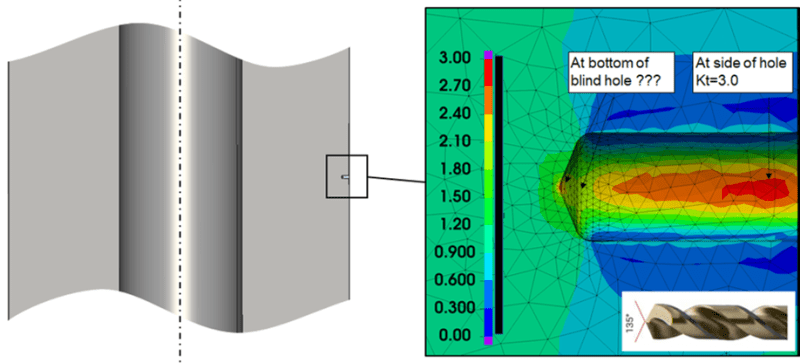
See the figure.

Given the geometry of the drill for the hole there are sharp corners at the bottom of a blind hole. In the figure the sharp corners at the bottom of the hole are modelled with a 1mm radius. In reality the corners are sharp or nearly sharp. If modelled sharp the FEA the stress results would of course be singular. This makes the blind hole more difficult to evaluate at least with stress based assessment.
Questions:
-What method could be used to evaluate the fatigue strength of such a notch at the bottom of a blind hole?
-Alternatively – are there perhaps references that say that the side of the hole (see figure) is the worst position and not the notches at the bottom of the hole? I have found one[1] but it is for aluminum and for very small holes and may not be relevant for larger holes in a steel shaft. In my case a 1/4" (6.35mm) hole.
-Or are blind holes worse that through holes?
Your inputs to this are very welcome
.
BR/Micke
[1] Geometrical size effect in the fatigue life predictions of aluminum wires with micro holes using methods of the critical distance, Engineering Fracture Mechanics, Volume 209, 15 March 2019, Pages 147-161
Is it a good idea to drill a hole in a shaft subjected to rotating bending fatigue load? Just kidding. However transverse holes in shaft (radially drilled holes) exist and need to be assessed in view of fatigue strength.
My question is about blind holes. Hence holes with a limited depth. Through holes can be assessed by FEA or formulas e.g. according to DIN 743. But what about blind holes.
See the figure.

Given the geometry of the drill for the hole there are sharp corners at the bottom of a blind hole. In the figure the sharp corners at the bottom of the hole are modelled with a 1mm radius. In reality the corners are sharp or nearly sharp. If modelled sharp the FEA the stress results would of course be singular. This makes the blind hole more difficult to evaluate at least with stress based assessment.
Questions:
-What method could be used to evaluate the fatigue strength of such a notch at the bottom of a blind hole?
-Alternatively – are there perhaps references that say that the side of the hole (see figure) is the worst position and not the notches at the bottom of the hole? I have found one[1] but it is for aluminum and for very small holes and may not be relevant for larger holes in a steel shaft. In my case a 1/4" (6.35mm) hole.
-Or are blind holes worse that through holes?
Your inputs to this are very welcome
.
BR/Micke
[1] Geometrical size effect in the fatigue life predictions of aluminum wires with micro holes using methods of the critical distance, Engineering Fracture Mechanics, Volume 209, 15 March 2019, Pages 147-161
