Continue to Site

Eng-Tips is the largest engineering community on the Internet

Intelligent Work Forums for Engineering Professionals

  • Congratulations SSS148 on being selected by the Eng-Tips community for having the most helpful posts in the forums last week. Way to Go!

Bolt Analysis with results coming from ANSYS

Status
Not open for further replies.

Mateus_R

Mechanical
Mar 15, 2018
48
Hello everyone,

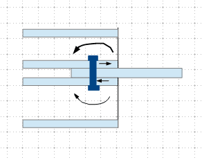
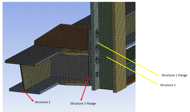
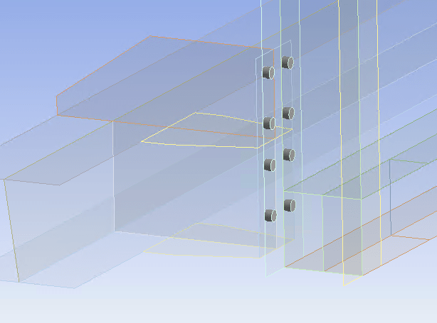
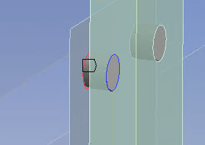
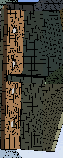
For a project I'm working, I have two flanges connected by bolts and I modeled the bolts as beam elements in ansys.
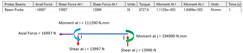
When I get the results from these beam elements, Ansys provided me 3 Forces and 3 Moments.
In this case, is it correct to transfer the bending moments coming from ansys as an additional axial force, or the axial force component already considers this effect?
This is not the case where I get a moment in the flange and I'm transferring to the bolts. These forces coming directly from the beam elements.
flange_bolts_gljkiv.png


Thank you in advance.
 
Replies continue below

Recommended for you

I think this is a modelling problem. You should release the rotational fixity of the bolt. The moment is expected at the plates/flange only.
 
Hi Mateus_R

I've designed a number of very non-standard connections using FEA, most of which experienced cyclic forces, I did them in Strand7 though.

How are you introducing an interface between the bolt other elements?
Are you allowing for contact, nonlinear geometry and material?

If your analysis is static it would easily to get rid of the fixities causing the moments, however the solution will be incorrect
If you are using non-linear static or non-linear transient dynamic analysis it becomes much more difficult(to achieve convergence), however through various conversations with Strand7 they have agreed with me on allowing the bolts to experience moments. The moments are generally small and only cause singularities which can be shown to be insignificant.

Note that localized effects around bolt holes may still not be accurate due to the fact that Rigid links (in your case RBE's) will over stiffen and allow for inaccuracies depending on the type of load.

If you really want to get rid of the fixities on the bolt I would suggest using a very large pre tension loads.
 
1) usually "better" to use CBUSH elements, so you control the bolt stiffness (use Huth).

2) Not sure what you mean by "These forces coming directly from the beam elements."

3) you could hand calc the moment, as a couple

another day in paradise, or is paradise one day closer ?
 
Sorry, just to add to my previous message, if you want to run a solution without some of the bolt fixities you can also develop stability by running individual loads and providing the correct fixities on the model to allow convergence, thereafter you can add the cases together in a single results file.
 
Mohanlal0488 said:
The flanges have a frictionless contact between then and the bolt (beam) is defined by the lines of each hole.

rb1957 said:
I mean that i'm not transfering the overturning moments acting in the flanges as an axial bolt force (Ex:4M/ND). The forces come directly from the beam probe.(

Could be a solution to release all the rotationals acting in the beam elements, obtain the forces (axial and shear) and then include the overturning moment acting on the flange as an additional axial force in the bolt?

 
"Could be a solution to release all the rotationals acting in the beam elements," … I don't think so, a fastener works by taking shear from one surface and reacting it at an offset surface. without moments it doesn't work. Moments should be at both ends as that's what happens in the real world (the offset moment is reacted by end moments under the head and nut).

another day in paradise, or is paradise one day closer ?
 
I do not understand, are you using some sort of links radiating from the circumference of the bolt holt to the centroid, and then having your beam elements (bolts) connecting to the centroids? How are you implementing frictionless contact?

There should be contact between the end plate and the flange of the supporting beam.

The moment aspect is normally neglected for structural calculations, as we only consider axial and shear forces based on codes. rb1957 is correct there is moment that occurs, it is normally small but it is there... You will struggle to get convergence without the moment in the bolts, unless you use some of the methods I described above, however they will force convergence for a solution which may not be 100% accurate.

Just a note, your bolt lengths play a big role in the moments, make sure they are correct. If you are using plate elements you can develop an accurate length based on your size of bolt and bolt hole...

 
I tried to perform some tests with the modelling of bolt elements as beams, in order to assess the bolts with some code check, but i can't figure out how to include this bending moments in the calculation.
In the image bellow you can find the reaction probe of the bolt simulated as beam element. I can't understand from where it comes from this moment difference, once when I tried to calculate the moment from the shear force the values are different.
bolts_test_i8iveb.png

I made an sketch with the forces/moments that I think are related to the probe values.
Any idea?

The length of the beam is 13.5mm and the diameter is 20mm. In reality i need to sum also the thickness of the shell elements (15mm)in the length, but I not sure if its relevant here.

From the probe values, which approach do you suggest to perform some code check? Consider only axial and shear forces and neglect the moments?
I'm facing this problem because the bolt is working also in shear. As Mohanlal0488 said, when working with axial forces the moments coming from probe is very small.

Thank you in advance for your suggestions.
 
Can you provide sketches that show the connection and connected parts, also indicate the applied forces?
 
r13, basically I have two rectangular flanges and the bolts that connects them are beam elements (line bodies). The flange is reacting to the movement of a structure. Unfortunatelly i can't provide you the full picture of the project.
The values I include in the topic were just an example of how ansys provide the Force/Moment probe for a beam element. From these values I'd like to assess the bolts with code check.
 
yes, you see your problem …
shear = 14000N
beam L = 13.5mm
moment reacted at each end = 14000*13.5/2 = 95000 Nmm …

so, your problem is by modelling a beam and then having to fix the ends your bolt is "sucking up" moment.
did you try releasing the moment ?

model fastener as an RBE and/or a CBUSH

another day in paradise, or is paradise one day closer ?
 
rb,

Just a note - the shears are opposite to each other, a couple, so the moment should be 190000 N-mm. Please correct me, if I am mistaken.
 
r13 said:
my situation is the following one:
flange1_mqjtm3.png

bolts_mfmm0k.png

bolt_edges_f0dpkv.png


The forces acting in these beam elements (bolts) are presented in ansys as the one I reported previously in the topic (axial, shear at I and J, torque, moments at I and J).

rb1957 said:
did you try releasing the moment ?
I can't use the end-release, since I don't have a line body. The beam is created from the edges of the flange shell element (as per image above).
rb1957 said:
model fastener as an RBE and/or a CBUSH
I have no idea how to model the fastener in this way, since I don't have enough experience with Ansys Mechanical. To do it I need to write some line of code? What is the benefit to using this approach (RBE or cbush)?
 
I think the flanges of structure 1 and structure 2 are "linked" (3D of freedom), not rigidly connected (6D of freedom). I don't know what element is available to model the rigid link.
 
It would be ideal, if you can eliminate the bending. But, IMO, it makes no harm if ignored, since the magnitude is such small. You can't ignore the shear though.
 
r13 said:
It would be ideal, if you can eliminate the bending. But, IMO, it makes no harm if ignored, since the magnitude is such small. You can't ignore the shear though.
I already use this solution (bolts as beam elemnts) in different applications where the axis of the bolt was aligned with the load, and in this case the moments were irrelevant. The problem arose when the axis of the bolt was orthogonal to the force (images above)
 
r13 … I took shears to be load and reaction

@Mateus … I'm not familiar with ANSYS. I have seen what you're showing and IMHO this is an awful corruption of FEA to fit to a CAD software for people who are "CAD-monkeys" (no slight intended). When you said "beam element" I thought of a 1D beam element, but ANSYS seems to be creating a bunch of rigid elements and doing some "witchcraft" behind the curtain and showing you some results.

ANSYS should have a rigid element so you can connect the bore of the hole to the center (commonly called "spider" element), ideally at the interface between the two parts. Do this for both bores, so you end up with coincident nodes. Then, ANSYS should have a "zero length" spring element to join the two coincident nodes, and then you can tune the stiffness of the connection from 1E7 down (or calc using Huth) and you can also tune the freedoms that you join … all 6 or only 3 translational.

another day in paradise, or is paradise one day closer ?
 
Status
Not open for further replies.

Part and Inventory Search

Sponsor