Continue to Site

Eng-Tips is the largest engineering community on the Internet

Intelligent Work Forums for Engineering Professionals

  • Congratulations cowski on being selected by the Eng-Tips community for having the most helpful posts in the forums last week. Way to Go!

Bolt Analysis with results coming from ANSYS

Status
Not open for further replies.

Mateus_R

Mechanical
Mar 15, 2018
48
Hello everyone,

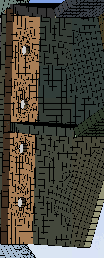
For a project I'm working, I have two flanges connected by bolts and I modeled the bolts as beam elements in ansys.
When I get the results from these beam elements, Ansys provided me 3 Forces and 3 Moments.
In this case, is it correct to transfer the bending moments coming from ansys as an additional axial force, or the axial force component already considers this effect?
This is not the case where I get a moment in the flange and I'm transferring to the bolts. These forces coming directly from the beam elements.
flange_bolts_gljkiv.png


Thank you in advance.
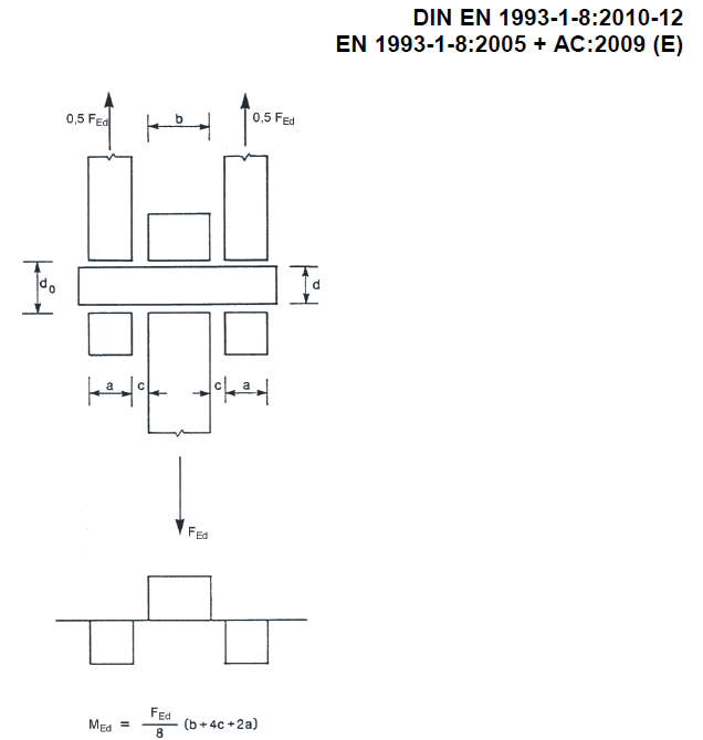
 
Replies continue below

Recommended for you

@rb1957 I was thinking to substitute the beam element by a Joint. In this way i can connect both holes and release the rotations.

@rb1957 Usually do you size the bolts (for standard applications) only considering shear and axial or do you include also bending? When I say bending, I'm refering to the bending caused by the shear stress.
I think that for small relations length/diameter (small bolts), calculate the stress due to the bending moment using the equation (Mc/I) is not accurate. Is it right?

Thank you for your support.
 
for a two member joint, I consider bending to be a conservative extra. The bolt is designed to carry shear, it's shear allowable is developed/verified in a physical test, so It understands the bending that physically happens. Remember too that as a bolt approaches it's limits the shear force "drifts" towards the parting plane, as the bearing stress starts "uniform" and becomes more triangular.

in a three member joint, particularly with a central packer, now the bolt has to develop bending to carry the load across the packer and I'd use a shear/bending interaction for the bolt strength.

another day in paradise, or is paradise one day closer ?
 
My opinion: This is a modeling error, I didn't quite pickup how you are connecting the beam element (bolt shank) to the face of the connection plate. Usually some sort of rigid spider is best onto a washer surface, with the three rotational DOF's released where the head contacts the connection plate.

I agree with rb1957 bolts are designed for shear and tension and don't typically develop pure moment. However, I do often design for an extra moment in bolts due to an offset shear, to account for a contact gap between the bolt shank and the plates. I usually use a small value <0.1" and don't see very many issues.

As for the "design" check to combine shear and moment your building code should provide guidance on that. Generally max shear and max tension from bending stress will be at a different point on the cross section, so you are likely safe just combining tension from bending stresses with pure tension for your design checks and keeping other variables the same.

Hope that helps some.

“Any idiot can build a bridge that stands, but it takes an engineer to build a bridge that barely stands.”
 
Thank you for your reply.

MegaStructures said:
I agree with rb1957 bolts are designed for shear and tension and don't typically develop pure moment. However, I do often design for an extra moment in bolts due to an offset shear, to account for a contact gap between the bolt shank and the plates. I usually use a small value <0.1" and don't see very many issues.
Like when you have a pin in a joint with clearance between plate hole and pin diameter? In this case I usually do a free body diagram and with the value of the bending moment i include a bending stress in the calculation to be added to the shear stress. This is what you refers as an offset shear?
 
This is much better suited and quicker to solve by hand than with a FEA model. If you need FEA for the structures I would split them into their own structure.
 
r13 said:
As I mentioned, I prepare a free body diagram and get the shear stress acting in the pin. If we have a double shear in a three body joints, I consider the external plates as my "reaction point" and the middle plate as the force one. Based on this, I draw the shear and moment diagrams and with the bending moment i calculate the bending stress using the equation: Bending Stress = M.c/I and then use Von Mises to account for bending and shear.
Here follows an extract from EN 1993 where you can see the same approach:
en1993_rhsc81.png
 
See my comment on "30 Sep 20 20:55", to which you didn't provide clear response, until now! For all its worth, the bending is ignored for bolted joint, provided the connection is properly tightened, c = 0, unless the gap(s) is provided for a purpose.

My question to you is how you ADD shear stress (V/A) TO the bending stress (M/S) for stress/capacity check, for which I've no knowledge of. The allowable shear stress is affected by the magnitude of direct tensile stress though.
 
@r13, there is a misunderstanding here. Your comment from 30Sep was answered with the image after the post, when you can see that my case was not a three body joint, was just two plates touching each other and some bolts to connect them.

This last topic with the image of EN 1993 where you can see the bending calculation is not related to my original post, is just a reply from the MegaStructures message.

r13 said:
My question to you is how you ADD shear stress (V/A) TO the bending stress (M/S) for stress/capacity check, for which I've no knowledge of.
I never said that I account shear stress to bending stress. I said before that I can combine Shear and Bending using Von Mises if I'm evaluating a pin.

Hope it is clear now.

 
but I think that's r13's point … why combined shear and bending stress together ? the maximum bending stress has (near enough) zero shear stress; the maximum shear stress has near enough zero bending stress ? Sure there are points inbetween with a combined stress but this is not normally checked or critical.

another day in paradise, or is paradise one day closer ?
 
I didn't get the turn of event !:) The picture in EN1993 does not apply to bolted connection though. The dimension "c" can occur between the outer ply of the plate and the nut when in the loose state only, even then, the bending will be quite small, as there is such limit distance for deflection.
 
Status
Not open for further replies.

Part and Inventory Search

Sponsor