Eng-Tips is the largest engineering community on the Internet

Intelligent Work Forums for Engineering Professionals

Bolt axial force. 1

Status
Not open for further replies.

takio

Mechanical
Jul 9, 2019
37
0
0
CA
Hello

Capture1_ddadh7.jpg

Capture_df45zc.jpg


Would anyone please help me with this calculation?
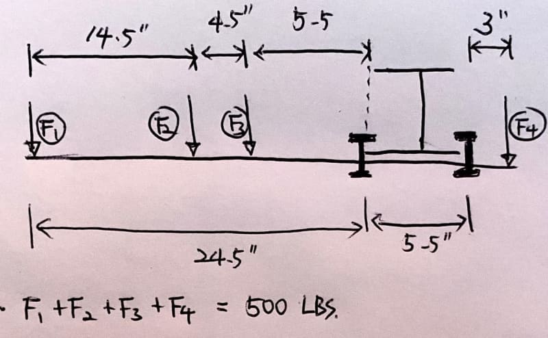
My goal is to know the proper preload for the 4 bolts that hold the I-beam and the beam structure together, using the clamps.
I used 5/8" grade 5 bolts.
and How to calculate the axial bolt force of the bolts? I ran FEA simulation and I would like to compare the simulation was run properly. so I thought I could compare the hand calculation of axial force to simulation result.
Please let me know if there need to be more information.

Thank you
 
Replies continue below

Recommended for you

@deserfox

Thank you for your interest in this post and the calculation.
I wanted to go for recommended preload from a manufacturer
I ran simulation (only with preload) and, it showed the safety factor of the bolt is ~1, based on von misess stress, (but when using axial load, it is 2.2).
I wanted to increase the bolt safety factor to 3.5, by reducing preload.

Thank you
 
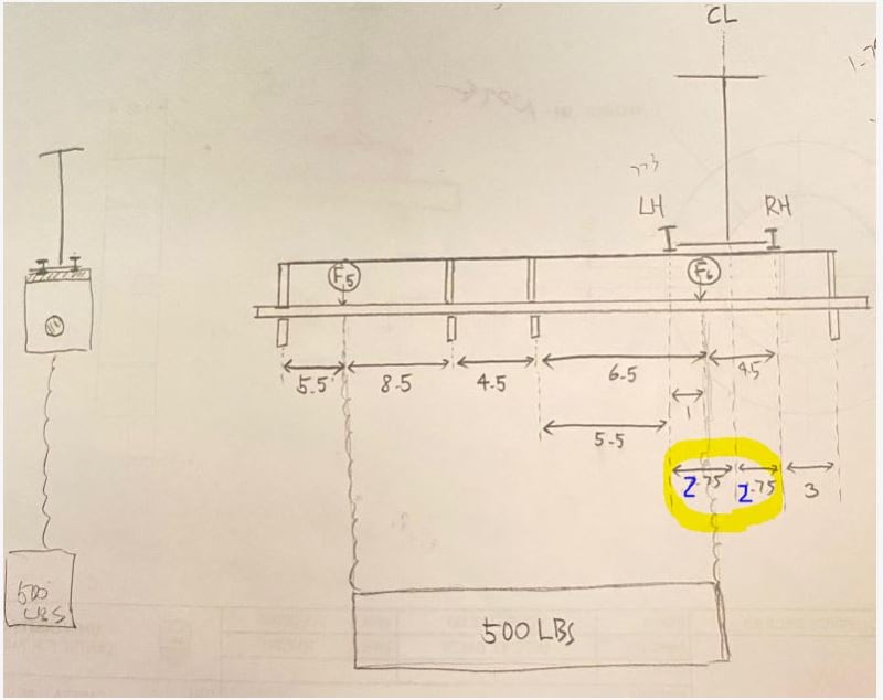
"1.75" should be "2.75" ... no?

yeah, I summed moments about two different points ... should've gotten the same result (obviously).

I think in my solutions the moments are calculated correctly ...
1) 250*23 is the moment at the CL of the joint,
2) 250*28.5 is the moment at the RH reaction (the RH clamp, 3" from the RH end) ... that looks right ! (the difference should be 250*2*2.75, no?)

I think I messed up with the bolt loads ...
1) LH load is 500/4 + (250*23/5.5)/2 = 125+523 = 648 lbs
2) LH load is (250*28.5/5.5)/2 = 648 lbs
the difference is in 1) I've moved the load (reaction) to the middle of the clamps, so I need to add the direct shear; in 2) I've summed the moment about one reaction, so the LH reaction * 5.5 equals this moment ... yes? (and I shouldn't've added the direct shear load)
this result is in line with desertfox's calc, once you 1/2 the load (500 lbs, not 1000lbs, for a reaction of 690 lbs).

the RH reaction is the applied load (500 lbs) less the LH reaction (2*648), so (500-1296)/2 = -398 lbs

If you want a SF = 3.5, use clamps good for 2300 lbs. Preload doesn't affect this ... assuming the joint has gapped (and released the preload) by the time the ultimate load is applied. I think you want to use something like 1000 lbs preload (to ensure the the compression side of the joint (the RH clamps) don't come loose).

another day in paradise, or is paradise one day closer ?
 
Hi

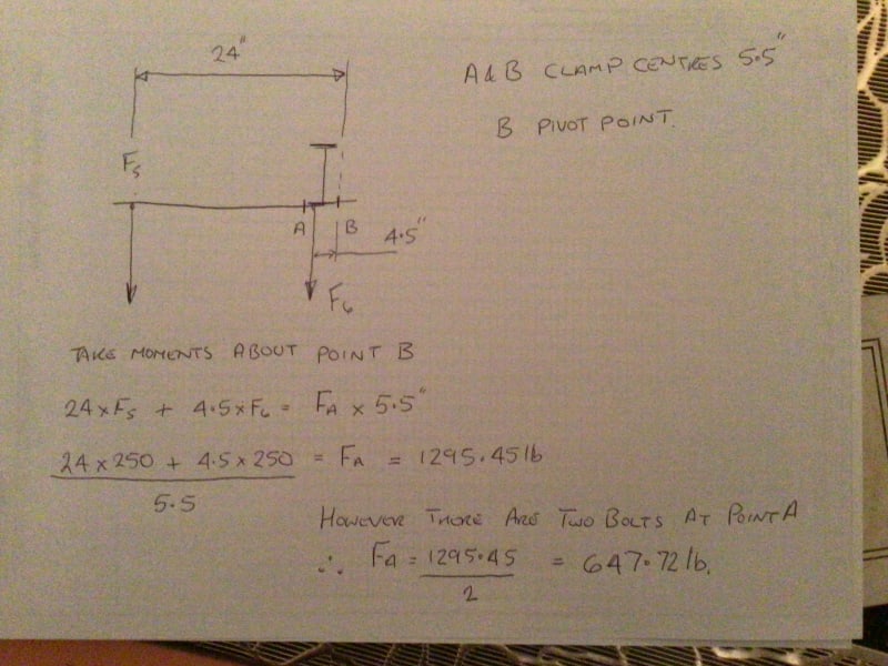
I have recalculated on the basis of the new information and posted my working out for the bolt load due to the external load offset below.
Need to add the direct load each bolt experiences which is 500lb/4 giving a max bolt load of 772.72lb.

E495D771-114A-471F-A412-4C8DE2532C4D_a8w55l.jpg


“Do not worry about your problems with mathematics, I assure you mine are far greater.” Albert Einstein
 
@YoungTAKI
You posted...
"I wanted to increase the bolt safety factor to 3.5, by reducing preload."

That is a misconception with bolting. When the bolt is preloaded (say to 1000lbs) the members (your W-beams) come in to compression. As the members become loaded the compression in the member gets countered by the load. The bolt sees a constant load of 1000lbs. This is good news - as the member is loaded and unloaded the members will see the fatigue loading while the bolt (typically weakest point) sees a constant load.

If the member is loaded beyond 1000lbs; the member will go in to tension and the bolt will begin to see additional load. This puts cyclical loading on the bolt and can increase failure. In general, it's better to increase preload to keep the load of the member below the preload value of the bolt.

This changes when the member is put in to compression (IE: if the load is put strictly left of the supporting W-beam the assembly will fulcrum around the LH bolt and the right side of the assembly will go in to compression.) At that point the bolt will see a reduction in preload as the members compress against each other due to the load. The bolt gets cyclically loaded but you don't necessarily have to depend on the bolt to support the load so the preload requirements decrease. Course this can change a bit if you're trying to swing the load around in circles or something. Then the bolts on the right side probably need to maintain clamp load to prevent assembly sway. A word of warning; if the compression load increases beyond the preload of the bolts then the bolts can come loose. That could cause a mess if the bolts shift then the assembly is loaded differently.

A lot of the lost preload due to compression becomes moot when appropriate safety factors are considered. I just wanted to chime in to make sure you don't try to increase loading capacity by decreasing preload. As for the discussion at hand, I think desertfox is on the right direction but the drawing confuses me more than pre-coffee morning can decipher.
 
Hi Rogue99

Actually although the additional load in the bolt is minimal the bolt load increases slightly when the external load is applied, consider the relaxing of the compressive stress on the clamped flanges and with the relaxation of the stress comes a increase in thickness of the clamped flanges as the flanges attempt to return to there original thickness, so this increase in thickness corresponds a further tensile strain in the bolt and hence additional tension to maintain equilibrium 👍

“Do not worry about your problems with mathematics, I assure you mine are far greater.” Albert Einstein
 
Agreed, I took the simplified approach that negates joint stiffness. I should have paid more attention to my own link to realize you were one of the main contributors!

Either way; grade 5 bolts at 5/8" can each support 14400 clamp load per eng toolbox. OP has 4 bolts. Estimates above show 1400lbs assuming the worst. I mainly wanted to prevent the OP from getting clever and putting on 50lbs of preload then showing up on a failures and disasters thread.

 
Hi Rogue99

No problem, good idea on your part regarding the OP👍

“Do not worry about your problems with mathematics, I assure you mine are far greater.” Albert Einstein
 
Hello rb1957

I can understand your 2nd approach very well. I appreciate it.
but, I still don't understand 5.5" to calculate load on LH. I still think it should be 2.75" which is the distance between LH and CL.
Is this your 1st approach?
1)Calculate Moment around CL.
2)When calculating load on RH, use distance 5.5" based on pivot point (LH)
3)Add direct shear load, (since the calculated moment location and pivot point to calculate a load on RH is different)

and, I messed up my drawing, it should have been 2.75" as below.
Capture1_kx2dav.jpg


Thank you
 
Hi YOUNGTAKI

You can’t solve the loads if you take moments about the CL there are to many unknowns.

“Do not worry about your problems with mathematics, I assure you mine are far greater.” Albert Einstein
 
well, IMHO, you can ... but it is less intuitive.

the moment about the center of the fasteners is reacted by a couple 5.5" apart, and there are two fasteners, so the load is M/11

another day in paradise, or is paradise one day closer ?
 
Hello @ desertfox @ rb1957

I am curious about the direct shear load.
I think the moment calculated from desertfox and rb1957 are identical.(rb1957's second approach)
but desertfox added direct shear load to the load calculated from moment.
and rb1957 didn't add the direct shear load.
 
my second solution I'm taking moments about the RH clamp, both applied loads and the reaction at the LH clamp ... so nothing to "add".

in my first solution I took (for whatever reason) the loads to the middle of the clamps (ie the loads, where they are, are equivalnet to a shear and a moment at the center of the clamps, yes?). so I have to combine the moment reaction and the shear reaction.

since I get the same result, it's a pretty fair bet that it's right !? as I've said already the 2nd solution is much more intuitive (for those of us who do it for a living).

another day in paradise, or is paradise one day closer ?
 
Hi YOUNGTAKI

Best way I can explain this regarding adding a direct load and not what you are calling a shear load, right if you look at my post with the diagram on posted earlier. I took moments about the RH clamp edge and the loads in the bolts have to balance the moment created by the offset loads and in addition downward forces have to be cancelled out by upward forces to maintain equilibrium, so I have 500lb force acting downwards which is shared equally across the four bolts ie 500/4 = 125lbs and so I add the 125lbs to the bolt force required to cancel out the moments

“Do not worry about your problems with mathematics, I assure you mine are far greater.” Albert Einstein
 
@Rogue909

Thank you for your comment.
I think what you are saying is that the bolt will eventually start feeling load, when the external load exceeds the preload.
then, this extra load will affect the bolt safety factor.
I actually read that the bolt safety factor should be higher than 3, when it comes to overhanging object.

5/8"-11 bolt. Grade 8.
Member : 1) ductile iron (clamp) 2) carbon steel (horizontal beam)

and I calculated below. (I assumed the two members are all carbon steel)

Preload = 5700 lbf (in order to use 90% proof strength,, It should have been 12880 lbf)
Yield factor = 3.32 (3.32 times more stress needed to get up to proof strength of bolt)
Load factor = 208.79 (208 times additional load can be applied and still be safe)
Joint separation factor = 30.86
Critical additional external load to separate joint = 7716 lbs

but the clamp manufacture recommends
5/8"-11 bolt. Grade 5.
Clamp FS = 5
Preload = 10440 lbf
Tensile SWL (PER BOLT) = 2219 LBS
Friction SWL (PER 4 BOLTS)= 877 LBS


In this case I thought preload 5700 lbf is sufficient enough, at least for tensile SWL.
but I am not sure about Friction SWL though.


Hello all

Thank you so much for helping me out.
I think I got hang of the load calculations!
I appreciate all the comments !

 
Status
Not open for further replies.
Back
Top