Continue to Site

Eng-Tips is the largest engineering community on the Internet

Intelligent Work Forums for Engineering Professionals

  • Congratulations waross on being selected by the Eng-Tips community for having the most helpful posts in the forums last week. Way to Go!

Bolt bearing - reduction for 'edge' distance in hollow sections (SHS/RHS) according to Eurocode?

Martin.H

Structural
May 19, 2021
38
Should 'edge' distance reductions (i.e. EN 1993-1-8 Table 3.4 Ab and k1 factors) apply to an bolt in a SHS/RHS member, when loaded towards that members radiused edge (aka corner)?

I put 'edge' in quotes as it's not a free edge subject to block tearing (as it continues around to the next face), but I can also imagine a bolt right next to a hollow sections edge radius won't perform as well as a bolt well set back from the edge radius when attempting to shear the bolt out the nearest side. I've not found any guidance on this.
 
Replies continue below

Recommended for you

EN 1993-1-8 Table 3.4 Ab and k1 factors are for bearing resistance and in your case AFAIK , you should use

- Ab is the is the smallest of Ad ; fu/fub or 1,0

- for edge bolts: k1 is the smallest of ( 2,8 e2/d0 - 1,7 ) or 2,5

The following doc. gives a brief info. for bolted connections.
 

Attachments

  • 02-GB_Bolts.pdf
    313.8 KB · Views: 4
Hi HTURKAK, I appreciate the response but you're just repeating what I said in my post :). The reference I gave is for bearing resistance, but the k and A factors within those formula's are allow for edge failure, aka tear-out, of a single bolt. Block failure of a group of bolts is covered elsewhere in the code.

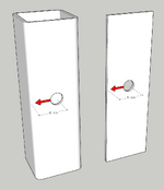
The formulas I referenced are assuming tearing out to free edges. For an SHS with a bolt loaded in the orientation I described, there isn't a free edge, the face just continues round to the next face of the box. This, combined with the stiffening effect of the radius, surely increases resistance.

To summarise: for the force direction in the image below, I don't believe the tear-out resistance of a bolt in a 5mm hollow section will be the same as the tear-out resistance of a bolt in a 5mm plate, all other things being equal. My question is how can this be quantified in design?

1731575312856.png
 
Last edited:
My understanding is , EN 1993-1-8 Table 3.4 Ab and k1 factors are for bearing failure mode. In your case , Clause 3.10.2 block tearing is applicable . The shear resistance of side wall could be added .

My interpretation ..
 
Always good to hear other's interpretations, it is appreciated.

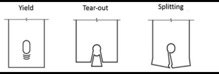
EN 1993-1-8 Table 3.4 might call it 'bearing failure', but in my view it's also considering tear-out and splitting failure.

Reasoning: Why would bearing resistance be anything other than a function of Bearing Area x Bearing Resistance? The bearing interface isn't aware of how close free edges are. The inclusion of factors based on edge distances in a 'bearing' formula can only be to allow for scenarios where bearing failure can't be reached because other single-bolt failure modes, i.e. tear-out or splitting, will occur first:

1731588679668.png


Regarding Cl 3.10.2, I'm not convinced the formulas or the diagrams make sense for the failure modes of a single bolt in the scenarios my 3d diagram above show.
 
I know nothing of Eurocodes. AISC splits the check into two equations - one checks tear out, the other checks bearing. The lower capacity is the controlling strength at the bolt hole.

BUT...is this really a bolted connection? Is this a blind bolt or do you have a nut inside somehow so the grip won't include and 'free space' and the bolt and nut head will draw the plies together with sufficient clamping force? Generally, that sufficient clamping force will crush a hollow member if you have the bolt head on one side and the nut on the other. In those cases, you should be looking at a pin connection, not a bolt connection. Bolted connections compress the steel around the bolt and it behaves differently than a pin. Referencing AISC because it's what I know and just to show the difference, bolt bearing capacity is defined as 2.4xFu, but bearing for a pin is only 1.8xFy.
 
Thankyou phamENG for pointing out the pin/bolt distinction, I had overlooked that and in my situation it is indeed relevant.
 

Part and Inventory Search

Sponsor