Continue to Site

Eng-Tips is the largest engineering community on the Internet

Intelligent Work Forums for Engineering Professionals

  • Congratulations SE2607 on being selected by the Eng-Tips community for having the most helpful posts in the forums last week. Way to Go!

Bolt capacity in hand-tightened condition

bugbus

Structural
Aug 14, 2018
505
Are there any situations in which hand-tightened bolts (less than snug tight, basically loose) can be relied on for structural capacity?

I am checking a steel-composite structure which is intended to be continuous for the future live loading. The beams are initially to be installed in a simply-supported arrangement, then a series of splice plates will be (loosely) installed, and finally a continuous concrete deck cast on top. The splice bolts would then be fully tensioned after the deck has been cast and cured, and the beams have taken up most of the deflection due to the wet concrete. The intention of installing the splice plates loosely is to prevent any unintended continuity of the girders until after the deck is cast and cured.

My question is whether the bolts can be relied on for structural capacity in this hand-tightened condition? We may end up needing to rely on them in the temporary case to provide restraint to the beams during construction.

Thanks in advance
 
Last edited:
Replies continue below

Recommended for you

I suppose attacking this from another angle - if these bolts are installed snug-tight (i.e., by the usual definition, installed with a spanner with the full force of a person) instead of hand-tight, is it realistic to expect that they would allow slip in the connection and to avoid loading up the splices?
 
I'd be going with LOOSE rather than snug tight. If you they are snug you can end up with a decent amount of friction. I've seen plenty of unintended moment connections from simple cleat plates don't up 'snug'. Sure in the engineering world this supposedly isn't a moment connection but when it is cantilever there is no doubting that it is BEHAVING as a moment connection. (Usually I've seen this lightly loaded structures that have not had any engineering.)
 
In the hand tight condition, they would theoretically have the same shear/bearing capacity as snug tight.

However, depending on the amount of deflection/rotation, the there could still be loading at the splices, if the bolts bear against the sides of the holes.

Another thing to consider is the sequence of the concrete placement. You may have to plan the direction/sequencing of the placement carefully to avoid movement of concrete that has already been placed and is starting to set, when concrete is placed in adjacent spans.

The whole concept is backwards of how we erect steel bridge girders. We want precise geometric control, so the girders are erected, aligned, and the splice bolts fully tensioned, before any concrete is placed. Of course, the splices for bridge girders are required to be designed for the full capacity of girder pieces they connect, so overloading them is precluded.
 
I agree with BridgeSmith . When you consider the failure modes ( Shear of the bolt, Bearing failure , • Block tearing ) still applicable except slipping . I will suggest splicing the flanges after casting and curing the concrete to avoid moment connection.
 
If you are less than snug tight, you have a pin and not a bolt. The bearing capacity at the holes will be quite different. The design values for the bolt itself will not change, though.

I'm really curious about why you're phasing it this way, though. Why not install the steel beams as continuous members and then cast the concrete on top? If you need to reduce stresses in the beam prior to concrete setting, why not prop the beams?
 
It sounds like you want the flange bolts to provide flexural strength and stiffness for resisting the live loads, but not for dead loads. Unfortunately (in my opinion) it will be difficult to ensure that the flange bolts (with standard size holes) will be completely ineffective resisting at least some of the dead loads unless perhaps you consider detailing the flange connections as bolted slip-critical connections with OVS holes in the flange plates.
 
The reason the bearing capacity is different for a pin is because you are expecting rotation, so you can't allow deformation at the hole. In this case, you still have the same bearing capacity as if the bolts were tightened, unless you plan to be letting the bolts spin around in the holes. The bolts being loose or snug tight makes no difference, so the question is if the slip in the holes (~1/32") and deformation from bolt bearing (unknown) adds up to enough rotation to call the connection pinned. This seems highly unlikely to me.
 
Hand tight is how snug tight works in theory anyway - with the bolts in bearing.

Why dont you want the beams continuous to start with?
 
The reason the bearing capacity is different for a pin is because you are expecting rotation, so you can't allow deformation at the hole. In this case, you still have the same bearing capacity as if the bolts were tightened, unless you plan to be letting the bolts spin around in the holes. The bolts being loose or snug tight makes no difference, so the question is if the slip in the holes (~1/32") and deformation from bolt bearing (unknown) adds up to enough rotation to call the connection pinned. This seems highly unlikely to me.
Hmm...we also have considerations for bolt holes where hole deformation is a concern and they have higher capacity than bearing strength for pins in holes. I was taught at some point that the compression within the grip of a snug tight bolt caused sufficient confinement of the surrounding steel to increase the capacity above that for a loose pin in a hole. Though, I admit, I'm having trouble finding anything to back that up now. And I can see where placing even stricter limitations on a pin to ensure the necessary freedom of rotation would make sense. I'll have to dig more into that...
 
That could be, if you find any material on this I'd like to read it. I'd guess that it should still be greater than the bearing strength of a pin though.
 
I am unaware of the jurisdiction, though I propose that loose is unlikely to be according to the specifications I am familiar with - AS 4100.
1. The AS 4100 specifications, that I understand is to control nominal actions according to the standard’s assumptions, are attached, and
2. If providing lateral restraint, this may not be according to the "minimum strength" specification, that is actually a maximum movement specification, simplified as minimum strength, refer attached.
 

Attachments

  • AS 4100 Supp1-2.png
    AS 4100 Supp1-2.png
    26.4 KB · Views: 10
  • AS 4100-1.png
    AS 4100-1.png
    177.2 KB · Views: 8
Hmm...we also have considerations for bolt holes where hole deformation is a concern and they have higher capacity than bearing strength for pins in holes. I was taught at some point that the compression within the grip of a snug tight bolt caused sufficient confinement of the surrounding steel to increase the capacity above that for a loose pin in a hole. Though, I admit, I'm having trouble finding anything to back that up now. And I can see where placing even stricter limitations on a pin to ensure the necessary freedom of rotation would make sense. I'll have to dig more into that...

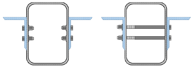
Here is an article addressing the pin designation:

I would argue that while it is true in HSS (large air-gap in the grip of the bolt), it is not the same for a typical connection that is hand tight. While not pretensioned, as long as the faying surfaces are in firm contact it would still mee the definition of a bolted connection (not pin) - but who is to say if the faying surfaces do in fact come into firm contact by simply hand tightening...
 
Here is an article addressing the pin designation:
That's the one! Thanks.


who is to say if the faying surfaces do in fact come into firm contact by simply hand tightening...
I think this is the issue. A snug tight connection achieves some pretension. Even if in contact, there won't be any meaningful pretensioning. In fact, I think that the OP is specifically trying to avoid any pretension and allow as much movement in these hands tightened bolts as possible.
 
Thanks all for the replies. I just wanted to respond to a few of the general questions in this thread.

The reason for this particular installation sequence is really not part of my review, I am only checking the temporary condition of the girders during construction. There are a few additional reasons for not installing the bolts fully tensioned before casting the deck slab, which are hard to explain in this short format so I did not mention them originally.

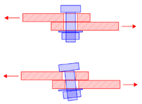
I also wonder if there would not be an undesirable bending/axial component in the bolt which would reduce its capacity, similar to the sketch below?

Screenshot 2024-11-25 142154.png
 
Last edited:
The reason for this particular installation sequence is really not part of my review, I am only checking the temporary condition of the girders during construction. There are a few additional reasons for not installing the bolts fully tensioned before casting the deck slab, which are hard to explain in this short format so I did not mention them originally.

I also wonder if there would not be an undesirable bending/axial component in the bolt which would reduce its capacity, similar to the sketch below?

View attachment 1449

I don't see any undesirable bending there unless there is significant plate separation then the failure mode will be in shear. Besides what capacity are those bolts on the flanges going to be running at? Isn't the whole point for them ideally not to engage even in bearing? If they are engaging then by definition don't have a simply supported condition.

Personally I'm less concerned about the bolts and more concerned about what the consequences are if a simply supported outcome isn't achieved. But like you have said it isn't part of your review.
 
Hello bugbus

Like othersI don’t fully understand the reason for that the assembly sequence but I am curious about how you would ensure how all the bolts are not in contact with any of the mating steelwork (around the bolt holes) even if the bolts aren’t fully pretensioned. My other question would be how would you know how much friction would be needed to achieve the desired affect?
 
The following may be of interest:
1. Fastener/pin ply capacity in bearing regarding ...sufficient confinement of the surrounding steel to increase the capacity..., refer attached, and
2. Fastener capacity with "loose fillers" as analogy regarding fastener capacity if not snug tensioned, refer attached, according to the following.

Guide to Design Criteria for Bolted and Riveted Joints


Attachments

  • Kulak-2.png
    Kulak-2.png
    80 KB · Views: 11
  • AS 4100 Supp1-1.png
    AS 4100 Supp1-1.png
    103.1 KB · Views: 11
@human909
You're correct that the whole point is to not engage the bolts (ideally). However, in the temporary situation before the deck is cast and the splice bolts are properly tensioned, we are looking at the option of these loosely installed bolts providing restraint to the girders mainly to resist accidental impact loads, etc. Without the bolts, the girders are only really restrained against horizontal loads by their own weight (friction) on their temporary supports. So, it is unlikely these loose bolts would ever need to be relied on for capacity, but it would be nice to know that they do have some reliable capacity. At the same time we are also looking at other options to provide temporary restraint.

@desertfox
The holes are oversized by the amount that the girders are expected to move during concreting, so there should in theory be enough room to allow the connections to slip. Although I'm conscious that this wouldn't account for initial installation tolerance. The bolts are then fully tensioned to be a friction type connection. I'm not sure what you meant by your last question sorry.

@PersonalProfile
Thanks for this, I will look into it. I'm also aware that in AS 4100, there is a reduction factor for bolts with fillet plates (I assume to account for additional bending in the bolts). I will see if this helps.
 
AS 4100's filler plate specification is apparently according to Kulak, according to AS 4100 Supp1 - attached.
 

Attachments

  • AS4100 Supp1.png
    AS4100 Supp1.png
    45.4 KB · Views: 7

Part and Inventory Search

Sponsor