Continue to Site

Eng-Tips is the largest engineering community on the Internet

Intelligent Work Forums for Engineering Professionals

  • Congratulations SDETERS on being selected by the Eng-Tips community for having the most helpful posts in the forums last week. Way to Go!

Bolt combine loading 1

Status
Not open for further replies.

DJCoutts

Marine/Ocean
Feb 25, 2016
14
Hi there

I'm currently trying to find a equation/formula to help show the applied for acting on a bolt and making sure its within the yield strength of the bolt.
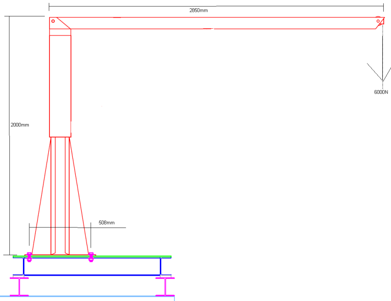
Bolt_connection_xuxvwz.png


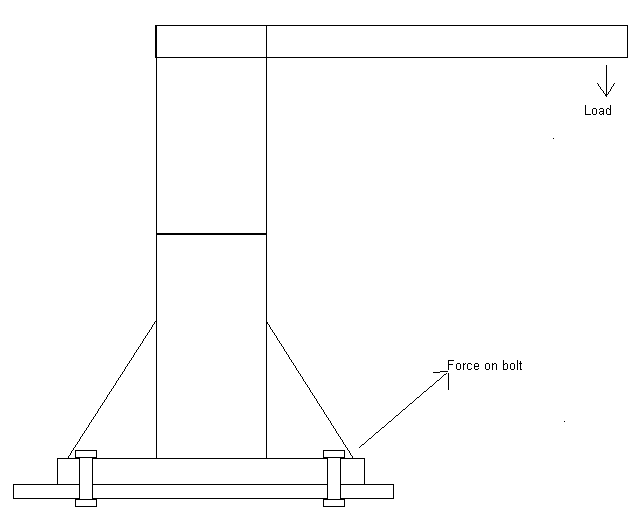
From the image you have a davit with a load on the end, this will then transfers the force onto the bolts.

Currently i have used the shear formula and tensile to get the individual loading as followed

e.g.

Load : 6000N
Bolt : 10mm
Yield : 400MPa

Shear (single shear)

tress = Load / A..............A = 3.14 x 5^2 = 78.5398mm^2............6000 / 78.5389 = 76.3943N/mm^2 (MPa))

As there are 4 bolts holding it down then i devied the stress by the number of bolts for get the individual stress on each bolt..............76.3943 / 4 = 19.233575 MPa

400 / 19.233575 = 20.79 factor of safety (FoS)

Tensile (same formula as single shear)

Stress = Load / A..............A = 3.14 x 5^2 = 78.5398mm^2............6000 / 78.5389 = 76.3943N/mm^2 (MPa)

As there are 4 bolts holding it down then i devied the stress by the number of bolts for get the individual stress on each bolt..............76.3943 / 4 = 19.233575 MPa

400 / 19.233575 = 20.79 (FoS)

As the forces is not acting on the axis or in a shear formation but at 45Deg, do i need to have the force applied in each direct at 50%?

Also in not sure how to combine there's to get the overall stress on the bolt.

Im also aware that the load will course the davit to rotate in some wear between the base and end of the davit arm

If anyone can point me in the right direction it would be appreciated
 
Replies continue below

Recommended for you

You show the load being applied at the davit arm, this creates a moment. You can decouple this moment to figure out the forces on your bolts. Some of your bolts will be in compression and some will be in tension. All four of your bolts will not be in tension so your tensile stress divided by four bolts is not correct.

Also where does your shear come from? You show an arrow showing a "force on bolt" which would put bolts in shear and tension. Where does this come from? Is this an external force? Because you do not get shear from your diagram from the 6000N load on the davit. You need to be clear on the Free body diagram.

Lastly, AISC has a check for combined shear and tensions. Doesn't sound like AISC governs in your area though.

 
andriver thanks for you reply.

I was trying to get a simple formula without going over the top with out having to do moment calculation, yes i know it not the bet way to do things.

due to not doing a moment, i estimated that the force would act towards the point of loading on the arm to make things simple.

if it helps the arm is 2.8m long and with the point being 2m high.

With this im going to two of the bolts in tension which are the ones at the back? for the one at the front will be in compression but not directly as the plate will have the load and ill be pushing against the base so with that are these not negligible and can be left out or do they need a different formula?

As my self im based in the UK and with this im support to help prepare equipment for a project to go on the vessel. this includes working out the load which something in going to lifted then calculating the stress on the bolt or weld, after that i pass this onto the vessel superintendent to make sure the vessel can have the devices fitted to the deck.
 
DJCoutts,

For someone in the UK I am having trouble following your English.

I am wondering what your qualifications are, as this is a very straightforward calculation. The formula you need to use is simple for an engineer, but your assumptions (load acting at a 45 deg angle) is way off so I imagine you are not an engineer?

A diagram with all the necessary dimensions and loads would be helpful as I am not following your description.

The davit will have a moment from a whatever it is lifting. This moment is equal to your load*distance from center of davit column to location of applied load. You can get the tension in your bolts by dividing this moment by the distance between your bolts. The tension can be divided by the two bolts that are in tension.

No where in your diagram do you show shear, you could probably get some shear from wind or a swinging load from the davit.

I do not think you understand the problem so I am hesitant to give any more advice as I assume you are not qualified to be making these decisions.
 
Thank again for your replay.

im sorry if you cant follow me as i have dyslexia so my grammar is not the best, I am an engineer i have a BEng Honers in operations engineering, my problem is that i don't do the calculation in my position at work, as it more to do with making sure the kit is ready and that is suitable to the working which is going to be carried out, with my dyslexia remembering the formulas is a lost harder but i do retain the understanding behind it.

Like i said, i was looking for a simple formula, This is something i would of used as well on bolt down winch's going to an a frame. but i understand now that due to the moment this will act completely different and the loading wont be equal over all the bolts.

Ill try this for the equation:

Bolt_connection_1_h2k8ue.png


Ill do the moment of the force:

Mast weight : 1745N
Boom weight : 863N
Load weight : 6000N
Bolt patten : 508mm square
Bolt : 15.6mm
Yeild : 400MPa

Vertical Load

W = Mast + boom + load......... 1745+863+6000 = 8613N


Moment

M = ((Force1 x Distant)+(Force2 x Distant)x sin(90)) davit at maximum radius.........((863 x 1425)+(6000 x 2850) sin(90) = 18329775 N/mm


Loading on Bolt

(M-(Wx204)) / 204 = Force........(18329775 - (8613x204) / 204) = 81238.8N...... with 2 bolts force will be halved = 40619.4N


Tensile stress

A = 3.14 x 7.8^2 = 191.03mm^2............40619.4 / 191.03 = 212.633N/mm^2 (MPa))

400 / 212.62 = 1.88 factor of safety (FoS)

Is this a better?

Sorry if it seemed that i did not know what i was doing but like i said my dyslexia dose not help me sometimes and with none of my notes trying to remember that right formula is challenging.
 
Now you we are getting somewhere. I could imagine referencing school notes with your condition would be a challenge..

I'm not sure where 204 comes from? Maybe you meant to say the spacing for the bolt patterns are 408mm (not 508mm you have shown), and 204mm is half of your bolt spacing?

I would Take the moment you calculated (18329775 N/mm) and divide this by your moment arm "d" Your moment arm "d" is the distance between your compression and tension anchor bolts (which is either 408mm or 508mm depending on what you meant). This can be divided by your two bolts, which is divided by the bolt area as you have done to compute stress.

You can throw some shear in there (if I have no actual loads I will add 5% of my design load in shear). Here in the US we use AISC code, and there is a combined check for shear and tension. I am not sure about the code in the UK.
 
Thanks for that.

Yes the distance is 508mm so it should read 254mm sorry about that.


18329775 N/mm / 508 = 36082.23N / 2 = 18041.1N

A = 3.14 x 7.8^2 = 191.03mm^2............18041.1 / 191.03 = 94.44N/mm^2 (MPa))

400 / 94.44 = 4.23 factor of safety (FoS)


I could add the shear stress but the bit im not sure is how you add the the tensile to the shear on a single bolt. This example 2 bolts will have tensile and shear and two with just shear.

Do i just add the two stress together or times them do to is acting over an area?

Yes my dyslexia dose not help and every time i come across a problem like this i make a detail excel calculation sheet showing step by step calculation on one tab and another tab being used as the input side.
 
For shear, you would likely engage all four bolts and therefore could use all four bolts to divide your shear stress. I am not sure what code you would use but you could just take the tensile UC + the shear UC and make sure those added together are less than 1.

94.44/400+shear/400 < 1
 
andriver

Thanks for the help and ill have a look over the shear as well

desertfox

thanks for the link i will have a check over this


Also looking over the moment acting on the end of the arm, would the mast hight also affect the stress? like a leaver action?

 
Hi

The affect of increasing the mast height will only affect the mass of the overall structure and the position of the centre of gravity at which the combined mast and boon mass will act as that will have a different position from the bolt rotation points to that of the load

“Do not worry about your problems with mathematics, I assure you mine are far greater.” Albert Einstein
 
Hello everyone,

I have some points to add here about this problem.

First, you cannot skip the moment force caused by 6000 N force. It is a remarkable moment.
Second, bolts are not mounted only to support the existing forces but to compress the counterpieces which are the base plates. This compress force is needed to prevent fatigue failure of the bolts.
If there are oscilating forces, the calculus are more complex. I would recommend VDI 2230 manual for bolted connections.

I hope that helps.
 

Thanks desertfox for the feedback understand what your saying just making use i'm not missing something

RafaelCosta thank you for your input and also the area which I need to look into for a better accuracy on my data.

I will also sate that the davit it self is off the self item with instruction of using 3/4 bolts grade 5 ( will check my calculation to make sure im using the MPa) for the mounting.

The load that im applying is the SWL of the lift wire and the davit it self can take 7562N.

The actual load will only be 600N so the whole set-up is way over engineered but have to show some calculation why is way over engineered.

I still have a couple of calculation to do for I.E the thickness of the plate being bolts to. as well as the base being bolted to the I beams.

Thanks again for your help in pointing me in the right direction, its slowing coming back to me.
 
Hi DJCoutts

If you assume all four bolts take the shear then you might be under estimating the shearing stresses in the bolts.
Consider how you would ensure that all four bolts would touch the edge of their respective holes on assembly, better advice would be to consider one bolt taking all the shear and if that's okay then the other bolts are a bonus.

“Do not worry about your problems with mathematics, I assure you mine are far greater.” Albert Einstein
 
Localized yielding of the plate around the bolts would allow for the even distribution of shear load to all of the bolts. At least in my eyes, and 95% of the other engineer's I've ever had a similar conversation with. This also jives with how Hilti Profis distributes the loading.
 
If the holes are clearence holes for M10 bolts then the will be around 12mm diameter, so if one bolt touched the edge of the hole on assembly and the other bolt was concentric in the hole,then the local yielding of the first bolt against the plate would have to be at least one millimetre.By this time the plates now have relative movement which isn't what the joint is designed for.
Also friction between the clamped plates will vary at each of the bolted points so again this will have an effect on any local yielding being uniform.

Perphaps you and the 95% of your colleagues might like to read this link:-

“Do not worry about your problems with mathematics, I assure you mine are far greater.” Albert Einstein
 
Hi desertfox

Thanks for the information, when i try and do bolt connection i always go for FoS of 3 as a minimum for main bolting load joints. ( it maybe over the top but in my eye its safer).

Ill add a 10% shear load to the set-up of the bolts as this will be on a vessel.

The base which its being bolted to is 3247N in weight so it got a decent counter weight for lifting 600N

The welding is then used to hold the base to the vessel.

Im also trying to do the bolt pull through calculation for the plate which is bolted to and im getting my self confused.

Currently im using the contact area of the bolt head (head flats - bolt shank) then times this against the thickness of the plate. but this gives me a volume, Im not sure where to go from here or that i have miss a part out for the bending of the plate??
 
hi DJCoutts

Well firstly when the davit is actually lifting it's unlikely to generate any shear load in the bolts unless it deviates from the vertical with vessel roll, I guess thats quite likely.

I normally take the area under the bolt head and divide it into the bolt preload and just ensure the clamped plates are not yielding.
If the plates under the bolt head are yielding then the embedment of the fastener will reduce the preload that your're trying to achieve.

“Do not worry about your problems with mathematics, I assure you mine are far greater.” Albert Einstein
 
Hi derertfox

Thanks for getting back to me, i think that getting me confused is that i'm using the specification of a plate being used:
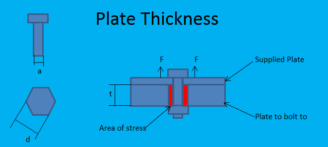
It has a yield stress over a range of thickness, obviously the thinner plate wont handle the same loading as the tick plate, i just want to make sure the head is not pulled through. (it wont but just need to show it)

Plate_k3puc1.png
 
Hi DJCoutts

First find the area under the bolt head, you can approximate by assuming the across flats of the hexagon bolt is a circle, then take the area of the clearence hole the bolt passes through and subtract it from the area under the bolt head.
Use the bolt preload and divide this by the difference of the two areas you calculated previously.
This should give you the approximate compressive stress on the clamped part, if the stress is high consider using a flat washer to spread the load.

“Do not worry about your problems with mathematics, I assure you mine are far greater.” Albert Einstein
 
Status
Not open for further replies.

Part and Inventory Search

Sponsor