Eng-Tips is the largest engineering community on the Internet

Intelligent Work Forums for Engineering Professionals

  • Congratulations waross on being selected by the Eng-Tips community for having the most helpful posts in the forums last week. Way to Go!

Bolt Head Pull Through in Steel 2

Status
Not open for further replies.

VTSE

Structural
Dec 20, 2018
7
US
Anyone have a resource for calculating the capacity of bolt head tear through (pull through) in a piece of a steel bar greater than 3/16". For instance, if there's a threaded rod in pure tension that is nutted on the backside of a flatbar. Limit states are available for the rod/nut, but I can't seem to find anything on the base material (thick steel). I know this limit state is touched on by AISI for CFS (and even NDS touches on it for wood), but I can't find anything on it for thicker steels. A calculation similar to punching shear seems reasonable; however, I imagine the failure mode would be some splitting of the bar, followed by a flexural failure on each side of the hole/split.
 
Replies continue below

Recommended for you

Not encountered that... you might use the perimeter of the bolt at t/2 all around and check that with the allowable shear... something of that ilk... maybe someone can suggest something better... maybe even FEM.

Rather than think climate change and the corona virus as science, think of it as the wrath of God. Feel any better?

-Dik
 
Some light gauge texts I have give formulas for "pull-over" for bolts/screws in steel. (And I can reproduce it here if you want.) But once you get to a certain thickness, limitations like prying and so on control. (As I understand it.)

 
post would be appreciated... info junkie at large...

Rather than think climate change and the corona virus as science, think of it as the wrath of God. Feel any better?

-Dik
 
Perhaps try different failure modes:
1) shear all around
2) triangular failure with 3 plastic hinges and 3 ruptures
3) shear arc with a plastic hinge on on side
4) ??
Seems (3) is most likely

Perhaps there is something similar to plate yielding in the section on HSS point loads.

 
I could swear that I saw something like this before. Looking at a perimeter that extends t/2 out from the bolt head (or washer plate) or something like that. Then taking the shear area of that perimeter vs the axial demand. Looking at base material shear rupture.

It sounds very familiar, but I don't think I ever did a calculation like this myself. I might have reviewed someone else's calculation or research paper.

For what it's worth, if it seems like it might be close using the nut head alone, then I'd use use a heavy nut and washer both to expand the shear area a bit.

 
A hex bolt will have stress concentrations at the corners, leading to loacalized tearing. A washer or flange nut should help. These connections strike me as not being ideal, for some reason the stress will be slightly more somewhere and that will identify the failure origin. Even laboratory setups seldom would see an idealized all-around punch-through failure. I see the failure much closer to localized shear leading to tearing then bending. Is it possible for you to rig up a test in a tensile testing machine?
 

Yes


Heeheheeheeheh... you WARose...

Rather than think climate change and the corona virus as science, think of it as the wrath of God. Feel any better?

-Dik
 
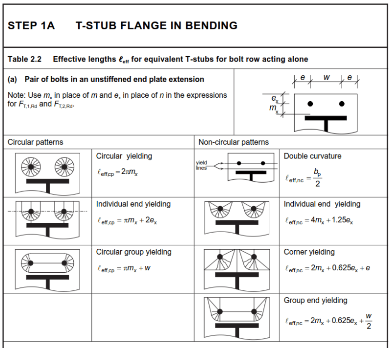
I think you can just use the equations for resistances of T-stubs? SCI document P398 (which provides an easier to read summary of EN 1993-1-8) covers this in detail and provides illustrations. You can check for all 3 modes of failure: Flange yielding, bolt + flange failure, and bolt failure. If flange yielding is all you're interested in then you need to calculate the smallest possible effective length for yielding:

Capture1_y7juxv.png


For a single bolt in isolation you might need to do some interpretation, but basically T-stubs can represent anything so it's decent thing to read up on, anyway.
 
Heeheheeheeheh... you WARose...

Ok.

In 'Cold Formed Steel Design' (3rd ed. by Yu, p.505), the following is given:

Pull-Out strength:

P[sub]not[/sub]=0.85(t[sub]c[/sub])(d)(F[sub]u2[/sub])

where:
t[sub]c[/sub] is the lesser of the depth of the penetration and the thickness of member not in contact with screw head
d=nominal screw diameter
F[sub]u2[/sub]=tensile strength of member not in contact with screw head

Pull-Over Strength:

P[sub]nov[/sub]=1.5(t[sub]1[/sub])(d[sub]w[/sub])(F[sub]u1[/sub])

t[sub]1[/sub]=thickness of member in contact with screw head
d[sub]w[/sub]=larger of the screw head or washer diameter (cannot be taken as more than 0.5")
F[sub]u1[/sub]=tensile strength of member in contact with screw head

Notes: These values would have to be modified by Φ or Ω (depending on if ASD or LRFD is used). The section also calls for min. washer diameter of 5/16" and min. washer thickness of 0.050".

The section on bolts also references this pull-over value.

 
Thanks... gentlemen...

Rather than think climate change and the corona virus as science, think of it as the wrath of God. Feel any better?

-Dik
 
Thanks everyone for the inputs. WARose has the correct equations for CFS, but wouldn't cover thicker steels. I briefly reviewed the document jaskamakkara suggested and I think that limit state covers different yield lines for yielding of the plate for prying action (which is covered a little differently in the states so it took me a little bit to recognize it). I think I'll run some numbers using the three failure modes that AaronMcD suggested. JoshPlumSE, please let me know if you ever come across those calculations again and can find a technical reference in them.
 
Update for anyone else looking for this answer: After letting this stew, I came across a formula in section 3.2 of AISC DG 24 regarding the strength for pull-out of a single fastener through an HSS wall as rn=Fu(0.6*pi*dw*t) with phi = 0.67 and omega = 2.25. Looks like this is just a punching shear check with some higher safety factors applied.
 
Status
Not open for further replies.

Part and Inventory Search

Sponsor

Back
Top