Continue to Site

Eng-Tips is the largest engineering community on the Internet

Intelligent Work Forums for Engineering Professionals

  • Congratulations waross on being selected by the Eng-Tips community for having the most helpful posts in the forums last week. Way to Go!

Bolt load capacity after tightening 15

Status
Not open for further replies.

Nordic8

Mechanical
Jan 8, 2021
6
Hi all,

I hope its not a stupid question, or if it is then maybe someone can point towards that "simple and obvious" answer that I'm failing to see here! Here goes:

I haven't got much experience with bolted joints, so far simple guidelines such as VDI2230 have helped me out just fine.

However, now I was trying to use VDI2230 for determining the tightening torques for a bolted flange and came across something that I fail to make sense of.

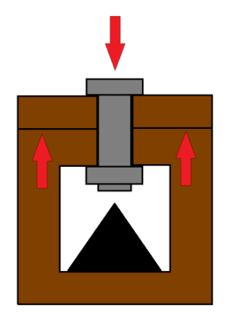
I'll give you a simplified description. It's a pipe with a flange, and an end cap bolted onto it to seal it off. Lets say it has 4 bolts that are evenly spread along the diameter, or 90degrees apart from each other. The holes in the flanges are not threaded, just bolts through and and nuts on the other side.

I'll use the VDI2230 method for calculating these bolts, following the procedure I found in a Würth publication.

Based on the diameter of the pipe and maximum working pressure I have determined that the maximum force on the cap will be 9.2 kN, that makes 2.3 kN per each of the 4 bolts. Therefore the axial operating force Fa = 2.3 kN.

As I have no shear forces to consider, the assembly preload force Fm = Fa = 2.3 kN. This will be my starting point.

Let's say I want to use grade 8.8 bolts. Looking at the VDI2230 table, the next closest load there is 2.5 kN -> size M4 is specified for 8.8 bolts.
Add one step for static concentric load -> 4.0 kN -> M5
Add one step for tightening with a torque wrench -> 6.3 kN -> M6

So the bolts that I need are grade 8.8 size M6.

I will estimate the coefficient of friction to be 0.11. The next closest step in the guidelines I have is 0.10, so lets got with that.

Based on all this, VDI2230 advises me that the tightening torque would be Ma = 9.0 Nm, which would create a 10.4 kN preload force in the bolt. It is said to utilize 90% of the screws yield strength.

Based on my calculation, the breaking load of a M6 8.8 coarse thread bolt at yield strength (640 MPa) is 11.29 kN.
10.4 / 11.29 = 92%, so that's just about right.

But... the assembly is not pressurized when I'm tightening those bolts. By just tightening them, I've already used up 92% of the bolts' reserve, not much left for when I will actually pressurize it.

If i will now calculate how much pressure this assembly can take after tightening the bolts, then I can only use the reserve left in the bolts (8 percent to yield strength) as in my calculation? That's not much...

Or lets give you another really simple example just to illustrate the point I'm trying to make here:
Lets say you have an M6 eye bolt, you insert it through a hole in a rigid steel plate in the ceiling, and screw a nut on the other side. If the nut is not tightened, then you can hang 11.29 kN load on your eye bolt before it breaks, but after you've tightened the nut according to VDI2230, you can only hang 11.29 kN x 8% = 0.9 kN off it before it snaps!.

I'm kinda confused here. What am I missing? All the example calculations I have seen for pressurized flanges, lids, end caps on pressure vessels etc just use the full capacity of the bolts in their strength calculations. But how can I do that if I've already used up 9/10 of it???

Could I tighten the nuts to a lesser torque than specified? But wouldn't the flange then leak, and would the bolts rattle loose / become undone too easily?

Thanks for any feedback (or for proving me stupid, it that happens to be the case :)

J.
 
Replies continue below

Recommended for you

Hi r13

Yes there is some alternating stress post pre-load of bolt as we have calculated above, it certainly isn't zero, however the higher the pre-load the less the range of cyclic stress but if the pre-loads too high then the bolts can fail as the additional stress can take it above yield.
I see what you are saying though[smile]

“Do not worry about your problems with mathematics, I assure you mine are far greater.” Albert Einstein
 
desertfox,

The quote below indicates your correctness in describing this matter for mechanical fastening practices. What Dauwerda and I have described are civil engineering practices, that concerning pretension a bolt embedded in a solid medium, such as concrete, or rocks. As you can see these are two set of completely different applications that do not relate to each other, but the similarity in preload the bolt. The similarity ends there, as after the pretension, the manner of load distribution is, again, different. Sorry for my poor writing, hope you understand.

"When a load (weight) is placed on a bolt, it is limited to the amount of load the bolt can handle before failing. However, when a bolt is tightened against a material, it allows the bolt to distribute the force through the material, so the bolt itself only holds a portion of the load. This means that a bolt can hold a significantly higher load when the correct amount of tension is applied. That tension is known as preload.

Load – The amount of force acting on a fastener assembly

Preload – The amount of tension (compression) needed to distribute a load’s force throughout a fastener assembly

Working Load – The load placed on the assembly once ready to perform

Bolt Preload – The tension created when the nut is screwed onto a bolt to hold two materials together. When the tension reaches the optimal preload, the working load (load added after creating the assembly) placed on a bolt will be distributed into the installation materials, so the bolt does not take the entire load."

image_q1qyg8.png
 
Hi r13

I am sorry I cannot understand your last post.
However the original question by Nordic3 was purely mechanical and nothing to do with civil engineering practice, so if civil engineering practice was being discussed then it had no place here, giving information that doesn’t relate to the question serves no purpose.😀

“Do not worry about your problems with mathematics, I assure you mine are far greater.” Albert Einstein
 
"This means that a bolt can hold a significantly higher load when the correct amount of tension is applied."

well, I disagree with that statement. Preload does not increase the failure load of the bolt, since most joints will gap before failure.
I guess you could have a very very high preload with a very very flexible bolt and then possibly maybe the external load could exceed the bolt allowable, but this would be a very tricky joint to design and would need very tight control on the preload (not the typical +-1/3 with a torque wrench).

another day in paradise, or is paradise one day closer ?
 
rb,

IMO, that author was indicating the bolt only share a portion of the external load applied after pretension, thus the load can go much higher, if the preload is at the optimum level.
 
yeah, but that's not what (IMHO) the words say. the load the bolt can hold is not "significantly higher" because some preload is applied. The allowable load of the bolt (Ftu*A) is unchanged (for the vast majority of cases) by preload, as the joint will gap before the allowable load is applied.

I speculated that it may be possible to apply a very high preload (95% allowable) and to have a very high joint stiffness so that the load increase in the bolt is very low to that the joint may be able to support a load higher than the bolt allowable ... but I think it's unlikely.

another day in paradise, or is paradise one day closer ?
 
I too appreciate this discussion and everything that desertfox (and others) have posted.
I am going to once again try to clarify what my stance has been.

desertfox said:
In fact even your diagram is incorrect because the spring representing the bolt doesn't move until the external force exceeds the preload,

This is the disconnect I was talking about in my previous post.
This is not incorrect with the assumptions that were made (and noted in the diagram). The assumption is that the block is many times stiffer than the bolt or spring. That is, in the calculation you posted, the stiffness of the steel plates Kp is taken as infinity. If it is, your joint constant C becomes 0, the increase of force in the bolt is therefore 0, and the decrease in the clamp force is equal to the full external load. That does not mean that the bolt is not carrying the load of the external force. It means that as the bolt takes the load of the external force, it releases some of the clamping force that is causing load in the bolt, so that the clamping force is no longer causing a stress in the bolt. With an infinitely rigid plate this is a 1:1 relationship.
This is the point I have been trying to make regarding the load path.
To me, stating that the load is shared between the bolt and the clamped plates indicates a belief/understanding that tension is somehow transferred between the plates, when clearly it is not (maybe I'm the only one who interprets it that way?). The load path for any tension must be through the bolt, there is nothing else in the joint providing resistance to tension. The external load causes tension in the bolt, so does the plates resistance to compression (clamp force). The clamp force between the plates decreases when an external load is applied because the stress/force in the bolt that was previously causing clamping action is now resisting the external force and is no longer developing that clamp force. A decrease in compression between the plates (which is caused by the tension in bolt) due to an external force being applied is not the same thing as load sharing between the bolt and the plates (again, to me, and how I interpret that statement).

I also understand/recognize that in reality the clamped plates are not infinitely stiff. But starting at that point can help with understanding what is actually happening in the joint before complicating the issue more.

To determine how much an externally applied load will increase the tension in the bolt and at the same time decrease the clamp force in the joint is really a simple strain compatibility issue. As the bolt takes on more load it will elongate, as the bolt elongates it will release clamp load, at the same time the plates will expand as they are now under less compression. As long as the joint hasn't gapped, we know that the deformation in the plates is equal to the deformation in the bolt and can use that to determine actual forces. However, finding the actual strain in the clamped plates is not so simple, as the area that is engaged is not uniform through the thickness or clearly defined. desertfox presented a method that is used for determining this. As hit on above, this is something that is typically ignored in structural joints but is considered in mechanical pressure vessel type joints. Prior to this thread, I did not know that it was considered in mechanical joints and I appreciate the education and information provided by desertfox.

 
maybe you'd be right ... if we could find an infinitely rigid plate. But damn'it we're stuck with these finite stiffness plates.

Yes, the joint clamp-up is much stiffer than the bolt and the change in bolt load whilst clamped is small (as I said a not unreasonable approximation is no change in bolt load) but we're trying to be precise. Once the joint is gapped, all the external load is carried by the bolt.

another day in paradise, or is paradise one day closer ?
 
Even in pressure vessel work they consider the elasticity of the bolt and that of the gasket , it is not assumed that the load in the bolt remains constant and they consider the joint and bolt stiffness similar to the calculations shown here.

see pages 59-60.


08/01/2021 desertfox said:
When you tighten the end cap on the vessel you tension the bolts but at the same time, the end flange compresses slightly against the end of the vessel, now when you pressurise the vessel the load is actually shared by both the bolts and the mating flange, the flanges are trying to release the compressive stress they are under which in order to do so must absorb some of the load and the remainder of the load is shared be the bolts. See this link I should of also said that the majority of the external load on a bolted joint is carried by the clamped members due to the fact that clamped members are usually much stiffer than the bolts.

According to your first post, my statement above was incorrect (which I took exception too)but you only cherry picked one line of the paragraph but I went on to say about relieving compressive stress between the joint faces and I have never stated that tension was shared between joint and bolt, what I have said is the the external force is shared between joint and bolt.
So if you are now saying you were considering the flanges to be rigid why did you not state this several days ago? because you argued with several posters here that the load was not shared. further to this you state:-

[08/01/2021 quote dauwerda]The tension in the bolt is 40kN
You start with a tension in the bolt that is 40kN, this is resisted by the compression between the two faces of the joint, also equal to 40kN.
You apply an external load of 30kN. The bolt still has a tension force of 40kN, however to maintain equilibrium, this means the compression force between the faces of the plates is now only 10kN.[/quote]

Reading your statement it seems very similar to what I said originally but you said I was wrong??


“Do not worry about your problems with mathematics, I assure you mine are far greater.” Albert Einstein
 
Are you even reading what I am writing? Are you trying to understand it at all?

Your first paragraph is repeating what I just said in my post, not sure why it is written like I said something different than that.

I didn't state that I was assuming a rigid plate because the op did it for me (as I pointed out earlier.)

I really don't understand what your sticking point here is? Once we cleared up the rigid issue the only other thing we disagreed about (and the only thing we disagreed about initially), was the statement:
"I think you are assuming that all the load when your vessel is pressurised is carried by the bolts and that is not correct."
I didn't disagree with anything else in your initial post (which you just quoted above), I don't understand why you think that I did or do disagree with it.

Yes! Exactly! I cherry picked the statement that I believe is misleading! I didn't quote anything else because I agreed with it!

You keep quoting me like I have been changing my tune on things, meanwhile I feel like I just keep repeating myself over and over. The only issue I had with your original post was the issue I brought up. I have explained why I believe it to be misleading multiple times above. If that statement works for people and helps them understand how the joint works, great. It doesn't work for me, and that is all I have tried to explain/bring light to.
 
rb1957 said:
Once the joint is gapped, all the external load is carried by the bolt.

Unless there's prying. Then load in bolt is higher than the external load. But let's not go there in this post....
 
Dauwerda
Am I trying to understand it ???
Remember I wasn’t the one charging in to this thread copying a part of someone else’s post and then stating that they were wrong, you managed that by yourself, but then you actually realised that, it was you who was wrong. This followed several days of silence whilst you try to justify your position and then returning and posting claiming that “oh I was assuming the vessel flanges were rigid”. Next we also have your statement “the bolt is the only load path” again totally wrong. There is nothing in the OP’s post that states the flanges were rigid.
I wrote that Nordic8’s confusion I believed was generated by the fact, that when the external load was applied, he thought the bolts took the full amount of the external load and that is not correct,I then stated most of the external load goes into reducing the compressive stress generated at the flanges and smaller amount goes into stretching the bolt to accommodate the relaxation of the flange faces, it
appears that everybody else except you,understood that.
In my opinion you have changed your story on one hand you are saying the bolts took all the load then in the next minute you are saying some of the external load relieves compressive stress at the flange interface.
Rb1957 even, put in a post saying you guy’s are saying they same thing but you even argued against that, so I suggest that you reread the posts and understand what people were saying to you.

Finally it might pay in the future before cherry picking peoples paragraphs and claiming they are wrong to get the full facts before posting, as this saves valuable time and doesn’t get people’s backs up.


“Do not worry about your problems with mathematics, I assure you mine are far greater.” Albert Einstein
 
desertfox said:
Remember I wasn’t the one charging in to this thread copying a part of someone else’s post and then stating that they were wrong, you managed that by yourself,
I didn't state that you were wrong. I stated that I disagreed with one of your statements. This leaves it open for me to be wrong just as much as it does for you to be wrong.

but then you actually realised that, it was you who was wrong. This followed several days of silence whilst you try to justify your position and then returning and posting claiming that “oh I was assuming the vessel flanges were rigid”.
I actually pointed out the rigid assumption disconnect in my post that is time stamped,9 Jan 21 13:41. This was simply the following morning after my previous post. Here is what I said, "Ok, now I understand one disconnect. I was assuming the stiffness of the flanges was much greater than that of the bolt as alluded to in the second example in the OP. If that is true the increase in the tension of the bolt is negligible (which your equations show)." Sorry if this didn't clearly depict the rigid assumption, I thought that it did.

Next we also have your statement “the bolt is the only load path” again totally wrong.
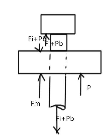
No, this is not wrong. This is our sticking point. Please take a look at the FBD below (initially provided by, goutam_freelance) and show me where or how there is any load path for the external load other than through the bolt.
image_vemtmf_efkvm4.png


There is nothing in the OP’s post that states the flanges were rigid.
Here is the statement in the OP that I am referring to (highlight is from me):
"Or lets give you another really simple example just to illustrate the point I'm trying to make here:
Lets say you have an M6 eye bolt, you insert it through a hole [highlight #FCE94F]in a rigid steel plate[/highlight] in the ceiling, and screw a nut on the other side. If the nut is not tightened, then you can hang 11.29 kN load on your eye bolt before it breaks, but after you've tightened the nut according to VDI2230, you can only hang 11.29 kN x 8% = 0.9 kN off it before it snaps!."
So yes, the OP did include this assumption to help with the overall concept.

I wrote that Nordic8’s confusion I believed was generated by the fact, that when the external load was applied, he thought the bolts took the full amount of the external load and that is not correct
Yes, and this is the statement that I disagree with. It implies that there is some other load path for the force to take. There is not, see above.

I then stated most of the external load goes into reducing the compressive stress generated at the flanges and smaller amount goes into stretching the bolt to accommodate the relaxation of the flange faces, it
appears that everybody else except you,understood that.
I did not disagree with this statement. I disagreed with your first statement. This statement does not support your first statement, here is why:
What is causing the compressive stresses generated at the flanges? The bolt is.
Why does the bolt stop generating these compressive stresses? Because the bolt is now resisting the external load.
That is, some of the stress in the bolt is now being caused by 100% of the external load and the rest is still being caused by the remaining clamping force.

In my opinion you have changed your story on one hand you are saying the bolts took all the load then in the next minute you are saying some of the external load relieves compressive stress at the flange interface.
That's just it, this is the same story. The bolt is no longer providing those compressive stresses because it must resist 100% of the load. The bolt stiffness constant is not assigning a percentage of the external load to the bolt and a percentage of the external load to the flange. It is determining how much excess stress is created in the bolt based on relative stiffness's compared to the initial unloaded condition. Or, if you go back and look at your example, you determined the final condition has 47.698 kips of tension in the bolt. 30 of those kips is because it is transferring the external load. That means the clamping force between the plates is now only 17.698 kips as opposed to the initial 40 kips.

So, in summary, The bolt does resist 100% of the load, but in doing so it stops creating as much of a clamping force between the plates. The increase in force due to external load and decrease in force due to the release of clamping combine to form an overall net gain of tension in the bolt that is determined from the bolt constant, which is based on the ratio of the stiffness of the bolt to the stiffness of the bolt plus the stiffness of the plates.

Finally it might pay in the future before cherry picking peoples paragraphs and claiming they are wrong to get the full facts before posting, as this saves valuable time and doesn’t get people’s backs up.
Again, I did not claim that you were wrong. I stated my disagreement, leaving it open for discussion to be hashed out.
 
I've been following this thread, and I think this whole disagreement is just based on confusion regarding terms. Someone, at some point, said something to the effect of 'the mating flange and bolt share the applied load' which seemed to start this giant discussion.

'Share' is the problematic term. The load experienced by the bolt and the load experienced by the flange are related, but the aren't 'shared'- they have opposite signs. Two bolts on the same flange DO 'share' load- in that the load applied to the flange is split 50-50 (in a perfect world) between the two bolts. Ultimately the bolt/flange interaction is really not that complicated if you look at the interaction in terms of balancing the forces.

Say we have a flange clamped by a bolt. The bolt applies (for easy math) a load of 10,000 kgf to the flange (10,000 kgf of preload); the bolt stretches 1mm to apply this load (so the bolt has a spring constant of 10,000 kgf/mm), and the flange compresses 0.01mm due to compressive stress from the bolt preload. (So the flange has a stiffness in compression of 1,000,000 kgf/mm) Other than bolt preload, initial load on the flange is zero.

Assume the flange is compressible but infinitely stiff in bending (flange bending makes this much more complicated).

Say we then apply pressure to the back of the flange sufficient to create 1000 kgf of load on the flange.

This reduces preload on the flange to 9,000 kgf. The stiffness of the flange in compression is 1,000,000 kgf/mm, so the strain of the flange due to compression load is now 0.009mm

In order to maintain equilibrium, the increase in strain in the bolt must match the reduction in strain in the flange- so the strain in tension of the bolt shank must be 1.001mm; knowing what we know about the bolt, this gives us a bolt tension of 10,010 kgf.

This tells us a lot of things that as engineers we already know; namely, that the ratio of stiffness between the flange and bolt matters, a lot. It also tells us something that structural engineers know well, but that mechanical engineers often forget, which is that the less stiff something is, the less load it will attract. If we reduced the stiffness of the bolt (by, say, extending the grip length by any arbitrary amount)we would actually reduce the magnitude of the increase in tension in the bolt shank, without affecting the performance of the joint at all (because we would still be providing 9000 kgf of tension on the flange in the loaded condition).

Say we take the same imaginary scenario, but we increase the stiffness of the bolt by a factor of 10:

-Bolt preload: 10,000 kgf
-Bolt stiffness: 100,000 kgf/mm
-Bolt strain due to preload: 0.1mm
-Flange stiffness: 1,000,000 kgf/mm
-Flange strain due to preload: 0.01mm

-Applied load: 1,000 kgf (no change)
-Remaining bolt preload: 9,000 kgf (no change)
-Flange strain due to remaining preload: 0.009 mm (no change)

-Bolt strain in loaded condition: 0.101mm
-Bolt tension in loaded condition: 10,100 kgf

By making the bolt 10 times stiffer we've made it attract 10 times more load. In most cases bolt/flange stiffness ration doesn't matter that much, but it's easy to see that in certain edge cases it can make the difference between joints that are robust and joints that aren't.
 
Well that's what makes the world go a round. it's very informative with all of the comments, if this is the right terminology, the stiffness & the flanges or what ever is as or maybe more important than the bolts or as important to equally work as well. lol I personally have more understanding. Bolt and other fasteners has been around since the beginning of time and some are to this day are functional. it amazes me with the controversy of the subject. is it getting to be a lost science or art.
 
On the 8th Jan at 21:19 time stamp I clarified my statement regarding my comment about the bolts seeing all the load, it clearly states that adding the external load and pre-load together is not correct which is in line with what everyone else said as far as I can see, see copy of quotes below.

desertfox said:
My absolute agreement with you rb1957

I stated this in my first post but it seems to have been ignored by dauwerda

Quote (desertfox)
now when you pressurise the vessel the load is actually shared by both the bolts and the mating flange,

[color ][highlight #EF2929]My reference to all the load being carried by the bolts was that the external load on the vessel due to the internal pressure plus the bolt preload was the total load in the bolt and that is not correct but I believe thats what the OP thinks.[/highlight][/color]
example two plates 10mm thick clamped together with an M16 bolt and a bolt preload of 40KN which is then subject to a external load of 30KN what is the total tension in the bolt dauwerda?

No dauwerda the bolt tension won't remain the same.
Quote (dauwerda)
The external tension load (again, this is the pressure on the end cap) will reduce the joint compression and the bolt tension will remain the same.

So really that should of been the end of the matter but when then have this statement from dauwerda:-
dauwerda said:
Quote (dauwards)
The load is most definitely carried by the bolts, there is no other load path

However on my post the 10th Jan I posted a diagram from Instar which clearly shows two load paths on a pre-loaded joint under a tensile external force, it goes on to say that the main load path is in the clamped parts and that the bolt is not the main load path.

I would suggest dauwerda that if you want to continue this discussion we start another thread rather than clutter this one any further.


“Do not worry about your problems with mathematics, I assure you mine are far greater.” Albert Einstein
 
"By making the bolt 10 times stiffer we've made it attract 10 times more load." ... I don't think so. the load portioning (if sharing is a bad word) between the bolt and the joint depends on the ratio of the bolt stiffness to the joint stiffness.

so in the first case we have kb/(kb+kj) and kj/(kb+kj), and in the 2nd it'd be (10*kb)/(10*kb+kj) .NE. 10*kb/(kb+kj)

another day in paradise, or is paradise one day closer ?
 
rb1957 said:
I don't think so. the load portioning (if sharing is a bad word) between the bolt and the joint depends on the ratio of the bolt stiffness to the joint stiffness.

Yes- but as long as the joint stiffness is much larger than the bolt stiffness (which it should always be), the total change in ratio is near the multiplier on the bolt stiffness. As bolt stiffness and joint stiffness converge the magnitude of the total change approaches 1, but if you're operating near that limit, most of the time that means you're building a very bad joint design.

Ultimately my point was at attempt at speaking in generalities- if you calc out this stuff using Shigley there's more nuance.
 
Status
Not open for further replies.

Part and Inventory Search

Sponsor