Continue to Site

Eng-Tips is the largest engineering community on the Internet

Intelligent Work Forums for Engineering Professionals

  • Congratulations cowski on being selected by the Eng-Tips community for having the most helpful posts in the forums last week. Way to Go!

Bolt Query

Status
Not open for further replies.

daparojo

Industrial
Feb 25, 2010
36

Please could you review, and see if I am going along the correct lines.

I have a plate of 15 Bolts, and is subjected to Forces in the Fx, Fz and Fy plane. The forces can only act in one direction at anyone time. See attached diagram.

The undercut of the bolt (smallest area is 57mm)i.e. area,a = 2551mm2
The Bolt diameter in hole, D = 62mm, i.e. area A = 3019mm2
Number of Bolts, N = 15

By using the formula :- F For Shear Strength Of Material
------
A N


i.e. The worse case, Fx, the Shear Strength Needed For Bolt is 220 N/mm2

My Material has a Min. Yield of 650 N/mm2 UTS 820 N/mm2
Therefore, by Shear Strength of Material is 650 x 0.57 = 370 N/mm2 - Factor Of Safety of 1.4 (370N N/mm2/261 N/mm2)

The Tensile Required For The Bolt in Fy direction. a being the undercut, smallest area.

Fy
---------
a N

Tensile Stress in Bolt is 156 N/mm2 - So pretty low compared the Yield Of Material 650 N/mm2
But also, the Round Nut and Head Of Bolt will also help to hold the joint together in Fy direction.

Now I need to calculate the Load needed to help overcome the Forces.

Load = A x Shear Stress In Bolt (Fx - is the largest force)
Load = 667 kN Clamping Load Required (A Higher Initial Is Required To Stretch Bolt)

Total Load Across Plate = 665 kN x 15 = 10000 kN which seems ok as it obviously equals Fx

Now, would the bolts fail if the Loading was the same, yet the Fx force went up to say 13000 kN which is higher than the total Load ? Yet the Bolt Shear stress would go up to say to 287 N/mm2, but the clamp load remains the same, there will be less loading in the bolts then the force. Am I correct thinking that it won't fail due to the Shear Stress in Bolt/Material Shear Stress being well within limits?
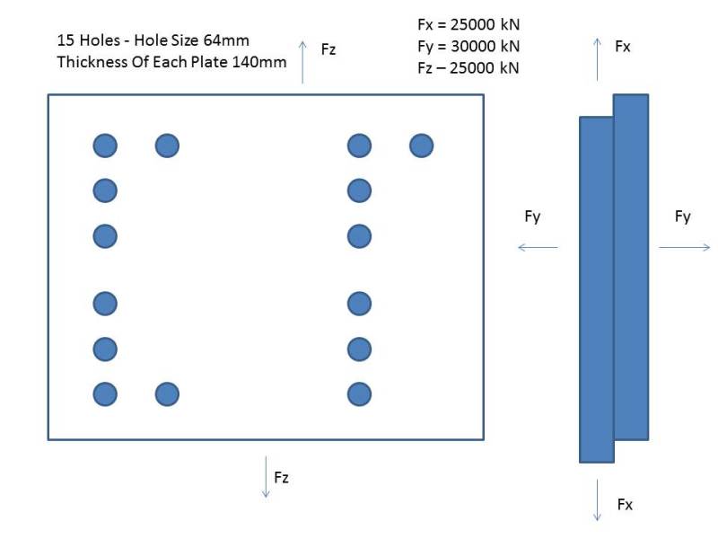


testter_u1fkhg.jpg


Many thanks
 
Replies continue below

Recommended for you

first, there's something wrong with your arrows, the way I read them at least ... you have y out-of-plane (ok) but x and z look to be the same in-plane direction.

second, you should combine tension and shear using an interaction formula.

third, I don't get "Total Load Across Plate = 665 kN x 15 = 10000 kN which seems ok as it obviously equals Fx" ... 665kN relates to the preload, a force in the y direction, but none of your forces equal 10000 kN ?

fourth, you need to combine the two in-plane forces to get the total shear load on the fasteners. maybe your shear is sqrt(2)*25000 = 35355 kN

fifth, how is the out-of-plane load being created ? pressure ?? is the pressure pushing the plates together, or pulling them apart ?

another day in paradise, or is paradise one day closer ?
 
yes, the French forces should be at 3 o'clock at 9 o'clock on the plan sketch.

Fy is pushing the plates apart.
The Fz and Fx forces occur as they are being pushed by a housing that is central to the plate.

What is meant by a interaction formula. I can understand that the bolt would be subjected to single shear at approximately 220 N/mm2 and with a preload of around 665 kN, subject to tension approximately 156 N/mm2.


the tension (or preload) and shear forces applied to a bolt interact. A common formula is ...
Rs = applied shear / allowable shear
Rt = applied tension / allowable tension
then RF^2*Rs^2+RF^3*Rt^3 = 1 and MS = RF-1

easier, and conservative, is MS = 1/sqrt(Rs^2+Rt^2) -1

another day in paradise, or is paradise one day closer ?
 
Hi daparojo

I'm not sure you are on the correct lines although your approach seems reasonable I'm struggling with your mathematics for example:- fy = 30000kN, now divide that by 15 and you get 2000kN load per bolt. Divide this force by the smallest tensile area:- 2000000N/2551mm^2 and that equals 784N/mm^2 which is over the 640N/mm^2 yield stress for the bolt material.
Also you are assuming that in the case of the shear force in the direction of x that the load is equally shared between all the bolts which in reality may not be true because how do you ensure that all of the bolts touch the correct side of the clearence hole on assembly, so it might be only 7 or 8 of the bolts carry the shear in practice. Further fx is given as 25000kN which if I divide by 15 gives a load on each bolt as 1666.67kN and the joint being in single shear then each bolt if the load was equally shared when have a shear stress of 1666.67kN/ 2551mm^2 which equals 653N/mm^2 which is much higher than the allowable.

One final thing is you should check is that the material that is clamped by the bolts can withstand the forces you are imposing on them, for instance the shear force transferred through the bolt could cause the clamped plates to fail in bearing.

Please check my maths in case I've made a mistake.

Desertfox

“Do not worry about your problems with mathematics, I assure you mine are far greater.” Albert Einstein
 
Thank you I will have a look and get back.
RF can be worked out once I calculate

Rs=220/370 = 0.59
Rt=156/650 = 0.24


ie MSN = 1
------------------------
SQRT(.59^2)+(.24^2)-1

MSN=-2.78 Therfore RF=-1.77
Does this seem right being negative values?

I think my head is fried looking at numbers all day :(


Am I on the right lines.
 
Cheers Fox, I did look at what you propose and went with a yield of 940 N/mm2 and then seem to shelve it as I thought I was over complicating things.
Sometimes you can look at equations all day and miss something. Thamks for your help.
In this case I have to presume all the bolts will share load and shear ie fitted type bolts.
 
agree with desertfox, hopelessly down.

mind you, you can salvage something by saying the shear is not felt on the minimum area, that the area for shear stress is closer to the 64mm hole diameter; still down though.

This should be easier to design ... bolts are readily available shear allowables (don't they ?). determine the shear load per bolt and pick a size that'll give you some margin (for the tension).

and isn't that a rather large undercut ? undercut diameter 57mm, bolt shank dia = 64mm

another day in paradise, or is paradise one day closer ?
 
Hi daparojo

I'm not sure what you are trying to calculate in your post just after mine although it looks like some kind of reserve factor or safety margin which I guess shouldn't be negative.

I would recommend that you increase the number of bolts and reduce the size down and spread the bolts more evenly, your sketch appears to have a lot of unbolted area in the central region of the plates.

It's getting late here now and like you my brains tired but the design should also look at the friction generated between the clamped plates and the effect of bolt preload under the other external loadings that the joint will see, I'll try and post some stuff tomorrow.

Thanks for your confirmation Rb1957 it's much appreciated.

“Do not worry about your problems with mathematics, I assure you mine are far greater.” Albert Einstein
 
Having a sleep on what as been posted above, I am having another train of thought.

With the Bolt having a Clamp Force on the two plates, i.e. 0.65% Of Applied Load (What I've proven in a workshop test i.e. measuring elongation at applied load, lock the nuts, and then measure the extension to give a % retained load.

With the plates moving in either x,y or z direction, the clamp force will take some of the shear force away from the bolts, at this time there is not enough info on the plates as they are away at manufacture.

So in the worse case, the Max Shear Force would be (I have changed the material)

Fx
---------
A N


The worse case, Fx, the Shear Strength Needed For Bolt is 552 N/mm2 (my maths was wrong earlier)

My Material has a Min. Yield of 900 N/mm2 UTS 1100 N/mm2

Therefore, by Shear Strength of Material is 900 x 0.57 = 513 N/mm2 - Factor Of Safety of 1.07 (552 N N/mm2 / 513 N/mm2) - As long as the Fos=1 or more it's ok

Am I correct to assume that if the nuts were just nipped up i.e. no loading, and the plate move in the X direction the Bolts will not shear as calculated? (Worse scenario?) With a load applied and retained, this would help the situation as the clamping force between the plates would also carry some of the shear force. Therefore the loading per bolt can be less than (25000kN/15 = 1667 kN ? Or does it still have to equal this figure?

With the Tension Force Fy, then the smallest area has to be taken into consideration i.e undercut.

The undercut of the bolt (smallest area is 57mm)i.e. area,a = 2551mm2

So at a loading of 1667 kN / 2551mm2 = 653 N/mm2 Tensile Stress
[highlight ]The Force is more in the Fy direction, but the nuts would take some of the tensile force away from the bolt?[/highlight]

With the Yield of Material being 900 N/mm2 = FoS = 900 N/mm2 / 653 N/mm2 = 1.37

However, if I cannot get a retained load of 1667 kN but a load of say 1500 kN, would this still work i.e. taking the theory that the clamping load on plates will take some of the shear away from bolts?

I still had this theory I was over complicating things.

Thank you for your help and input
 
hi
I stated in my last post about the friction between the clamped plates and yes that will help the situation, however friction coefficients tend to be unreliable and so at the outset you need to decide whether you want the friction to carry the shear load or your bolts to absorb it and design accordingly.

I will post more later.

“Do not worry about your problems with mathematics, I assure you mine are far greater.” Albert Einstein
 
Cheers Fox,
To take the safe option I would say its the bolts that would take the full shear load.

Thanks for the help
 
Hi daparojo

A couple of points I wanted to share with you earlier:-

Firstly unless I am reading it wrong the bolts still fail in shear because the allowable stress is 513N/mm^2 and yet your shear calculation shows the stress 552N/mm^2, now I guess you could argue that the friction between the plates might well be the saving grace but I would be happier sticking an extra bolt or two into the joint.


Secondly the tension on the bolt of 1667kN is the external load and the preload for the bolt should be about 30 to 50% above this to ensure that the joint doesn't part when the Fy force is applied.

I'll post again shortly with some more information

“Do not worry about your problems with mathematics, I assure you mine are far greater.” Albert Einstein
 
980 N/mm2 is the yield of the material I can now get which pulla the shear strength 0.57 x 980 = 558 N/mm2
 
so you've changed material and got a (yield) shear allowable of 558 vs an applied shear of 551 MPa. doesn't leave much margin for tension load ...

another day in paradise, or is paradise one day closer ?
 
Hi again

I've just noticed that in your earlier posts the 1667kN was the shear load and not as I read it in your last but one post as the tensile load, the tension load with 15 bolts is 2000kN per bolt and in order to ensure the joint doesn't part under the load in the Fy direction the bolt preload should be about 30 to 50% above the external load so that would mean a bolt preload of 3000kN per bolt, I doubt that your increased bolt material will stand that because 3000kN / 2551 = 1176N/mm^2.
Now if you get the bolt to accept 3000kN per bolt you will get a total contribution force of about 9000kN in friction to resist the force in Fx direction.
As I see it at the moment I think you haven't enough bolts in the joint to resist those forces, in addition you need to consider the clamped plates for strength, for example consider a bearing failure in the 10mm thick plate, which is bolt hole diameter x plate thickness giving an area of 62 x 10 mm^2 = 620mm ^2 and divide this into the 1667kN whichever yields 2688N/mm^2 stress.

I now conclude your whole joint wants a redesign.


“Do not worry about your problems with mathematics, I assure you mine are far greater.” Albert Einstein
 
cheers fox. I will evaluate and have a redesign on what has been noted. personally I do think the forces are quite high. I will keep you updated.
 
Ok, having a rethink and redesign, I am going to put an extra 5 holes when it comes back from fabrication - 2 on the left and 3 on the right.

Fy = 30000 kN
N = 20

Load Per Bolt = 1500 kN - Retained Load i.e. 30000 kN / 20 Bolts
Applied Bolt Load = 2300 kN Approx. - Normally 65% of Applied Load is Retained. i.e measure elongation at stretch and then again with the nuts locked tight and the pressure removed.

Tensile Area Of Bolt At Smallest Section i.e 57mm, area, a = 2551mm2

Tensile Stress Of Bolt = F/A = 2300 kN / 2551mm2 = 901 N/mm2 at Applied Load
Tensile Stress Of Bolt = F/A = 1500 kN / 2551mm2 = 588 N/mm2 at Retained Working Load

The Applied Load Vs Min. Yield = 901/980 = 92% - Pretty Close To The Yield Point - I could specify a higher yield say 1020 N/mm2 if needed.
The Retained Load V Min. Yield = 558/980 = 56% - Well below 75% of the Yield Of The Material.

With this calculation, I am taking away the possibilty of the friction of the plates taking some of the shear load.

The Bolt diameter in hole, D = 62mm, i.e. area A = 3019mm2

Shear Area of Bolt is 3019mm2

Shear Force Through Bolt Fx and Fz = F/A = (25000kN/20)/3019mm2 = 414 N/mm2

Material Shear Load = 0.57 x Yield Material = 0.57 x 980 N/mm2 = 558 N/mm2

Factor Of Safety Of Shear Load Material V Shear Force Through Bolt = 558 N/mm2 / 414 N/mm2 = 1.34

Is this a better solution?

What I am getting confused with and need to get my head around is the following:-

If I just put the bolts in with no loading, and tightened the nuts by hand. Would the Shear Load Of The Material take the full Load in Fx and Fz?
By introducing a Pre Load, the Friction between the plates would lessen the Stress the Bolts would take in Shear.

The tensile force is necessary for the Fy direction.

Sorry for the many posts, but I am trying to learn as I am going along. Many thanks for all your help and patience.


Hi

Yeah the joints looking better and some of the shear will be absorbed in the friction but as you said in your previous posts you were ignoring friction.

What you need to do next is combine the tensile and shear stress to find the resultant stress on the bolt.

What you haven't done is looked at the clamped plates because I think you have a problem there still particularly as they are only 10mm thick.

“Do not worry about your problems with mathematics, I assure you mine are far greater.” Albert Einstein
 
Hi Fox, and thanks.
The plates are 140mm thick each one.

I take it that to combine the Shear and the Tensile Stress you add the two results together.

Shear Force Through Bolt + Tensile Force = 414 N/mm2 + 588 N/mm2 = 1002 N/mm2 - Is that correct? This is over the Yield but just below the UTS (1080 N/mm2).

Thank you for your help.
 
Status
Not open for further replies.

Part and Inventory Search

Sponsor