Continue to Site

Eng-Tips is the largest engineering community on the Internet

Intelligent Work Forums for Engineering Professionals

  • Congratulations KootK on being selected by the Eng-Tips community for having the most helpful posts in the forums last week. Way to Go!

Bolted Web Connections 1

Status
Not open for further replies.

Engineer John

Structural
Jun 2, 2023
7
Steel beams that are only bolted through the web are traditionally designed assuming they are pinned supports. If the connection were only say 4 bolts (2x2), any engineer would assume a pinned connection. However, say the beam is deep and there are a significant amount of bolts. Say a 2x10 bolt configuration. A bolted connection that deep would be able to resist some moment. So the question is: How many bolts can there be in a shear connection. before one can no longer consider it pinned? When can a large bolted connection be considered as a fixed support? Is there any guidance from any know sources regarding this?
 
Replies continue below

Recommended for you

IMO if there is ever any doubt your structure and its members should be analyses for the behaviour of pinned AND rigid connections. Though in VAST MAJORITY of cases, assuming pinned is a more conservative choice so for the structure.

I agree.

We typically ignore the crossframes or diaphragms in the structural model, i.e. we design the girders as if they react independently, using a girder line analysis. AASHTO requires the crossframes or diaphragms to be designed for all applicable limit states if they are include in the structural model. I would say without some very detailed FEA, to quantify the load on the connections with partial fixity, connected to girders and other components with flexural and torsional rigidity that also need to be quantified to get accurate results, the way to design the diaphragms and connections, is to assume a fixed connection, and assume pinned connections to design the girders.
 
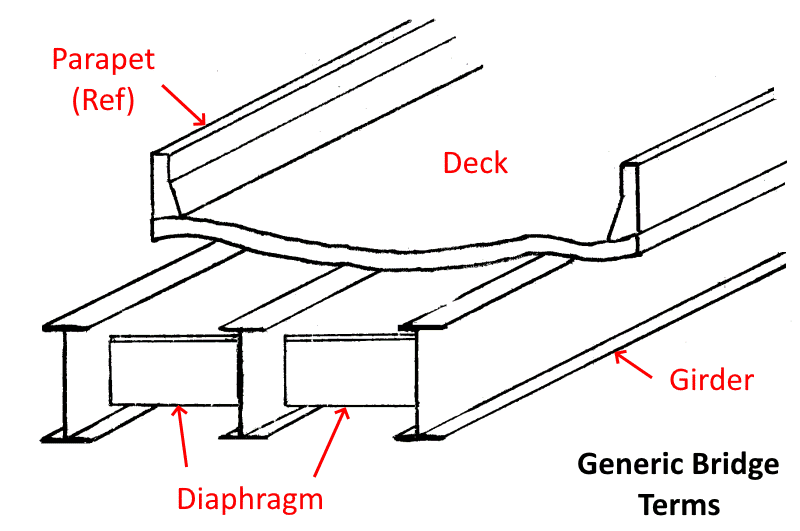
Since this thread is not in the Bridge Forum, the following is for engineers who are not familiar with the bridge terminology being used:

Bridge_Components-800_zjjq9o.png


Diaphragms are placed at intervals along length of girders. Diaphragms control girder LTB, especially during construction until the deck is placed. In the completed structure, diaphragms redistribute forces to prevent one girder from being overloaded.

The OP tells us: "The bridge is very wide with variable loading across it. The 3D bridge model resulted in high axial forces in the diaphragm..."
IMHO, force redistribution from the variable loading across width of the deck is probably the cause of the high axial force.
 
I appreciate everyone's responses on this thread. Thank you.
 
I agree with human909 that designing/checking the end connections for both pinned and fixed end conditions would be conservative and essentially envelope the problem. The problem here is that the magnitude of the fixed end moments we are seeing are relatively high, and will cause a significant increase in the size of the end connection and number of bolts that will need to be installed. As it currently stands, our bridge is 365 long x 643 wide and we have 1,185 steel plate diaphragms. As SlideRuleEra indicated, the extreme width of the bridge is causing very high forces in our transverse members, which is typically not seen in less wide, more 'finite' bridges.

The main issue here is that there seems to be no clear direction as to whether a deep bolted web connection can be considered a 'pinned' or a 'fixed' connection. We agree that due to the depth of the connections, there will be some moment transfer, but we just don't know how much that will be and we also don't think it will be near the same as a fully restrained moment connection. Section 10 of AISC Steel Construction Manual, Design of Simple Shear Connections, seems to agree with this. In the Force Transfer section, it states that "while simple shear connection do actually possess some rotational restraint, this small amount can be neglected and the connection idealized as completely flexible." Further in Section 10, for Single Plate Connection, there is a sub-section for 'Extended Configuration'. Again, this is referring to a simple shear connection and states that the procedure can be used to determine the strength of single plate shear connections with multiple vertical rows, and in the dimensional limitations, is also states that the total number of bolts is not limited.

Finally, in Section 10, there is another section on Shear Splices. Again, AISC considers at bolted web splice a simple shear connection. In this case however, AISC does discuss designing for an eccentric moment, however this is due to connection geometry, not direct applied moment.

AISC seems to consistently consider bolted connections through a web only as as simple shear connections and that the magnitude of moment transferred through such connections will be small and can otherwise be neglected. It seems like a lot of others disagree with this, which we can see how and why, however, we have not been able to find any other references for direction as to how best to treat or design these type of connections. Most of what we have found is vague and doesn't give clear direction.

Thank you for everyone's help and input on this!
 
The_Terminator said:
AISC seems to consistently consider bolted connections through a web only as as simple shear connections and that the magnitude of moment transferred through such connections will be small and can otherwise be neglected. It seems like a lot of others disagree with this, which we can see how and why, however, we have not been able to find any other references for direction as to how best to treat or design these type of connections. Most of what we have found is vague and doesn't give clear direction.

Go with conservative at both ends: what does the design require for moment transfer? Deliver it reliably per code/best practices. What CAN the design impose in undesired/nuisance moment transfer? Draw a conservative line and hew to it with defensible numbers drawn from best assessments. For example, what is a probable float on a fastener pattern, and how much beam deflection is required to deliver moment to adjacent connections? Are you really going to get that amount of deflection?
 
Can you reduce the stiffness of the diaphragms themselves, to reduce the forces in the connections? That's been a popular way to reduce the forces in the connections.

The other ways that this has been done is to offset the diaphragms, so that they're not in contiguous lines, or just simply leaving out diaphragms at some locations, to disrupt the continuity along the diaphragm lines. This allows the girders to twist a little, greatly reducing the forces transferred to the diaphragms, may also be an option worth considering.
 
BridgeSmith, we have tried both the methods you mentioned to try and reduce the forces in the members and connection, yet nothing has made a significant enough impact to be beneficial. We also don't really have the option to leave out diaphragms in the middle of the bridge where these very high forces are occurring due to the geometry and configuration of the structure. We did try staggering the diaphragms, but this didn't make as big enough of a reduction in forces as we would need. This is not what most would consider a 'normal' bridge, thus, we have been finding that a lot of the general rules of thumb and typical things you would do don't fully apply or work with a bridge that is as wide as what we have. The main thing we have found is that the bridge doesn't act as a finite width because it is so wide, so patterning loading transversely has a HUGE effect on the forces of the transverse members, i.e. the diaphragms, and why we have such large forces.
 
I wasn't suggesting leaving out diaphragms in the middle of the bridge, but leaving out lines of diaphragms between girders, i.e. 4-6 girders connected normally by diaphragms, and then one bay between girders with no diaphragms, and then another 4-6 girders connected, and so on.
 
There's some ways to estimate the impact the connection has on rotational stiffness.
[ol 1]
[li]Reduced cross section - Add short, rigidly connected members at the ends of your beams that use the depth and thickness of your connectors and are the same length as the distance from the face of the support to the center of your bolts.[/li]
[li]Bolt slip - Determine how much rotation occurs when the beam goes from its initial horizontal position (bolts align vertically) to their bearing position (top and bottom bolts pressing on opposite sides of the holes which are larger than the bolts). Remember there will be bolt slip in both the beam and the connectors. Once you know the amount of rotation, you can replace the beam end moment from your fixed support model with a concentrated moment that results in the amount of rotation that you calculated.[/li]
[li]Bolt plowing - When the bearing force is at 2.4dtFu, you get a hole elongation of about 1/4" (AISC 360-16, CJ3.10). You can determine the bearing force in your bolts (which should be less than 2.4dtFu) and estimate how much additional movement you will get from bolt plowing. Then do the same procedure I mentioned for bolt slip.[/li]
[/ol]

I would probably just start with the reduced cross section to see if that helps you enough to get things to work since it will likely be more accurate than the other estimations since it doesn't depend on the accuracy of the bolt hole fabrication, hole elongation tests, and if your bolts actually overcome friction and slip.

Still use fixed and pinned models to envelope the behavior, but this may bring down the difference between the two a little.

Structural Engineering Software: Structural Engineering Videos:
 
Bolt slip - Determine how much rotation occurs when the beam goes from its initial horizontal position (bolts align vertically) to their bearing position (top and bottom bolts pressing on opposite sides of the holes which are larger than the bolts).

I don't like assuming the initial alignment of the bolts. They may already be up against the sides of the holes when they're erected and tensioned, and therefore may not have any rotational movement capability due to bolt slip.
 
The Terminator said:
...a lot of the general rules of thumb and typical things you would do don't fully apply or work with a bridge that is as wide as what we have.

Could the bridge be designed as two (or more) parallel, independent, but adjacent, superstructures that share a common substructure?

 
Status
Not open for further replies.

Part and Inventory Search

Sponsor