Continue to Site

Eng-Tips is the largest engineering community on the Internet

Intelligent Work Forums for Engineering Professionals

  • Congratulations KootK on being selected by the Eng-Tips community for having the most helpful posts in the forums last week. Way to Go!

Bolted Web Splice Joint behavior 1

Status
Not open for further replies.

AK4S

Structural
Jan 2, 2015
98
I am involved in a discussion regarding the behavior of a Bolted Web Splice Joint and looking for some clarity to understand the true behavior of the connection.
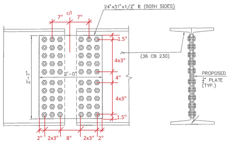
In an existing bridge(several simple spans), one of supports appears to have been constructed incorrectly (shifted by 3ft, whereas all other spans are of the same length). So a Bolted Web Splice Joint is observed in the beams of this span (span1).
Untitled_o0wrap.jpg

Splice detail:
Web_Splice_Sketch_apfiya.jpg

As seen above, there is discontinuity at the top & bottom flanges and the concrete deck above is also discontinuous at this location (expansion joint in deck directly above this splice). Hence it is my understanding that this connection is primarily a shear connection would resist shear and the resultant moment caused by eccentricity of the shear load.
i.e. The span 1 is equivalent of a hung span and the splice connection was never intended to take moment, i.e. the beams were not continuous.

The argument I have received from a colleague is that due to the size of the connection, the rotation of the beams is restricted and hence the behavior will be more like a "partial" moment connection with the system behaving like a 2span continuous beam and the web-splice plate carrying/transferring the bending moment at this location.

I do not agree and feel that flange-splice plates are required to transfer the moment at this connection and a web-splice plate only is not adequate. So I would model the two spans with a "hinge" at the splice location.
Bending moments are primarily transferred through flange splice plates and moment transfer through web portion is not significant. See sketch below:
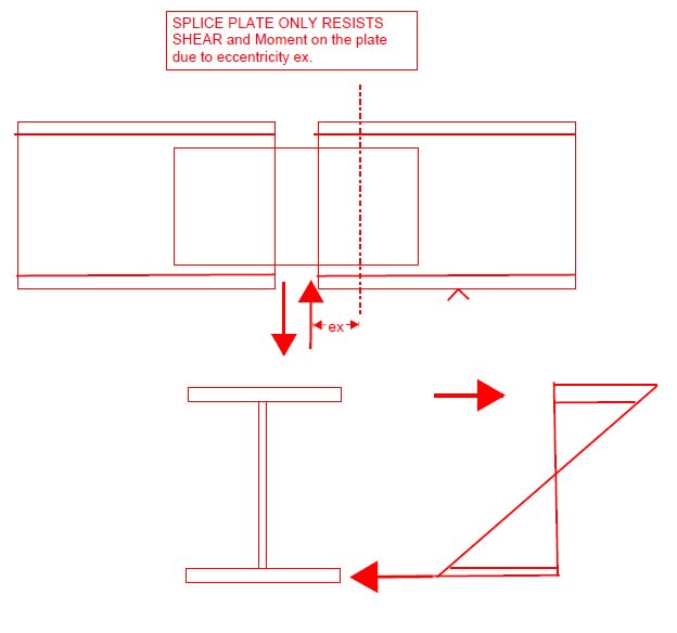
Untitled2_pqwq4d.jpg


[ul]
[li]Does the behavior change when you have a connection with so many bolts? Like the bolted connections are locked in with dead load and during live load the beam rotation is prevented thus transferring moment through the web-splice connection?[/li] I can understand this may not be a "pure Hinge" condition, But the moment transfer should not be significant to specifically check the web-splice plate to carry it and if so, what is the expected bending moment? carrying full moment through the connection is not valid. Any thoughts?
[/ul]
 
Replies continue below

Recommended for you

The argument I have received from a colleague is that due to the size of the connection, the rotation of the beams is restricted and hence the behavior will be more like a "partial" moment connection...

I do not agree and feel that flange-splice plates are required to transfer the moment at this connection and a web-splice plate only is not adequate.

Does the behavior change when you have a connection with so many bolts?

Seems you are asking if a heavily bolted connection performs as if it is slip critical, even though the connection was not designed to be slip critical.

My answer is a qualified "yes". I more or less agree with your colleague... partial moment connection. The only concern I have is that 1/2" thick splice plates on a W36 seem somewhat wimpy to allow allow numerous bolts to create a "good" partial moment connection.

You mention that "flange-splice plates are required to transfer moment". That is certainly optimum, but the web splice plates don't "know" that; the web splice plates just transfer as much moment as they are capable... which is probably enough for the loading diagram shown.

I've use heavily bolted connections similar to the one shown on W36 beams on a coal railcar unloader. There are always minor (but within tolerance) variations on bolt hole locations on mating surfaces. With a large number of bolts it is almost certain that these variations cause enough interference to make the joint almost immovable under load... unintentionally creating somewhat of a moment connection just from the interference. Proper bolt tightening just enhances the partial moment connection capability.

Edit:

...so, what is the expected bending moment?

Start by calculating moment at the splice location assuming the beam is two-span continuous.
Then see if the twin splice plates can resist that moment under ideal conditions (assume full moment connection capability for the splice plates).
The answer determines what calcs to do next.

 
I think we'd first have to know if it's slip critical. If not, it will rotate too much to take moment.

Even if it's slip critical, I think it can reasonably be simplified into a shear connection. In an overload condition, it will form a plastic hinge. It acts similar to a sacrificial seismic fuse. It's like putting a piece of tape to secure two rods together.

AK4S said:
Does the behavior change when you have a connection with so many bolts?

Yes, but I think the connection plate moment of inertia relative to the beam is more of a controlling factor. That's why I don't think the 2 span condition is entirely accurate; the moment could just die in the plate, not transferring the rest to the beam and making that end act like a cantilever. Two vertical plates' moment of inertia will be like 20% of the beam's. If you're only 3' away from the negative moment point, assuming 2 span will make the moment very high in the plate.
 
I agree with SRE and your colleague - it's a partial moment connection. Calculating how much moment it can transfer is fairly straightforward; calculating how much moment it will transfer is an entirely different and more complicated matter. You could spend a ton of time calculating relative stiffnesses, rotations, etc. to get some sort of approximation of the moment carried by the splice under a particular loading condition, but then there's numerous other loading conditions, for which it will carry a different moment and have a different effective stiffness.

I would do as SRE suggests, and assume a full moment connection...to check the design ratio/load rating of the splice. Then, lazy person that I am, I would assume it as a hinge to calculate the load effects on the remainder of the girder. If the controlling load rating is at a location other than the splice, then the splice doesn't control the capacity of the girder, and you can go on your way, knowing that you've 'left a little on the table' in terms of the actual load carrying capacity, because of assuming a hinge where there is actually some moment resistance. I can tell you this much from experience - you wouldn't get much of an increase with a refined analysis considering some stiffness from the splice.

Rod Smith, P.E., The artist formerly known as HotRod10
 
Partial transfer of moment, yes, but I would think it tends more towards being a pinned connection.

the right hand side bearing would be interesting - whether it has any uplift restraint.
 
It is a shear connection with moment capacity to resist the stress due to distortion (change of curvature at the pin joint).
 
Not my area ... wouldn't you want this to be fully effective (to carry the moment from the beam on 3 supports) ? Isn't that the conservative assumption ? And if you can get there with simple bolt group analysis, isn't this how the joint would work ? Of course the deflection of the bolts could be a factor when considering deflections of the beam.
Clearly this'd be the case (fully effective) if there were straps along the caps (moment continuity).

Shear only (ie a hinge) would be the conservative assumption for displacement, yes ?

So maybe assume both (at different times) ... what we call "overlapping conservative assumptions).

"Hoffen wir mal, dass alles gut geht !"
General Paulus, Nov 1942, outside Stalingrad after the launch of Operation Uranus.
 
I think it's pretty clear from the 4" to 5" gap between the beam ends and the lack of any flange continuity that this is intended to be a shear splice.

What are the shear loads at this joint? If the shear capacity of the plates or if n*bolt shear capacity*eccentricity factor from AISC tables (I'm assuming the zero moment location is the center of the gap) is close to the shear demand, then it's extremely unlikely this was designed to transfer even partial moments.

I would personally only be trying to make this transfer moment if I needed continuity to reduce the moments on the beams at a different location to get it to pass a check.

Please note that is a "v" (as in Violin) not a "y".
 
so analyze as though there is a hinge at the splice CL. Then this is the shear here, and at the beam attmts (fastener groups) there is shear and offset moment ?

Don't worry about the local deflection discontinuity, probably very small ?

"Hoffen wir mal, dass alles gut geht !"
General Paulus, Nov 1942, outside Stalingrad after the launch of Operation Uranus.
 
would you want a hinge in a bridge beam ?

"Hoffen wir mal, dass alles gut geht !"
General Paulus, Nov 1942, outside Stalingrad after the launch of Operation Uranus.
 
Makes the LHS beam effectively simply supported to simplify the analysis. If the splice was a bit further out it might have been taken to be an inflection point so moment capacity was moot, but OP says this appears to be a mistake in construction.
 
winelandv said:
If the shear capacity of the plates or if n*bolt shear capacity*eccentricity factor from AISC tables (I'm assuming the zero moment location is the center of the gap) is close to the shear demand, then it's extremely unlikely this was designed to transfer even partial moments.

Since this is a 'fix' for a construction error, it may not have been fully analyzed during 'design', so it's best not to assume anything with regard to its design. What is of concern is the loads, including moment, the splice actually carries, and what happens to it if the load effects exceed the capacity of the splice - does it yield and redistribute loads to other portions of the girder, or does it fracture?

Rod Smith, P.E., The artist formerly known as HotRod10
 
I'll grant that there is a lot of unknowns here - original bridge construction date (pretty sure those are Carnegie beam sections called out), why bolts and not rivets (if it's as old as I think it is), what changes have happened to the support geometry, what exactly is the OP doing here (trying to analyze the "fix"?, re-rate the bridge?, adjust span lengths?), etc. But, without bolted flange plates, I still think the design intent was to transfer shear.

This is all fairly moot, though, without knowing what kinds of forces the joint is being asked to transfer for both the moment-transfer and shear only scenarios.

Random Q for you Rod, would you submit a joint detail like this to a state DOT and expect them to sign off on it being a moment connection? I don't think it'd fly in my state, but the US is big with all kinds of quirks, so maybe it's different where you practice.

Please note that is a "v" (as in Violin) not a "y".
 
personally, I'd include cap straps, to restore as much strength as had been accounted for in the original design.

"Hoffen wir mal, dass alles gut geht !"
General Paulus, Nov 1942, outside Stalingrad after the launch of Operation Uranus.
 
I still think the design intent was to transfer shear.

It may not be the intent, but the reality is what it is. If it is carrying moment, that has to be considered in evaluating the capacity of the splice (the bolts, splice plates and web). It can conservatively be assumed as a hinge in the analysis of the girder.

Random Q for you Rod, would you submit a joint detail like this to a state DOT and expect them to sign off on it being a moment connection? I don't think it'd fly in my state, but the US is big with all kinds of quirks, so maybe it's different where you practice.
As the guy who would be reviewing it at the DOT, I can tell you definitively that I would not consider this splice configuration as a full moment connection. We always splice the flanges and web, and would be very skeptical if a consultant submitted this.

Rod Smith, P.E., The artist formerly known as HotRod10
 
Thank you for your responses. I ran some numbers and below is my summary:
[ul]
[li]Considering Simple spans & hinge at the splice location, splice connection as a shear connection to resist shear and the resultant moment caused by eccentricity of the shear load. For the splice plate, rating factor(capacity/demand)=15. The flexural strength of the beam (+ve moment at mid span) has a rating factor =1.5 and will govern.[/li]
[/ul]
[ul]
[li]Considering as 2 span continuous (without hinge) and assuming the web-plate to carry all flexural moment at the splice location, the rating factor= 1.4 for flexural yielding of the web-plate and will govern. I have to figure out and have not yet evaluated other checks (bolt group capacity, plate rupture etc) at this connection due to the applied moment.
Also there are few splices where the plate thickness has deteriorated to 70% remaining. For these cases the rating factor of the web-plates can be < 1.0. [/li]
[/ul]

Few other notes:
[ul]
[li]Sketch of the splice connection from Original construction (1990) does not call out for a slip critical connection. Also one of the beam splices was repaired (2006) after the original construction and the repair sketches do not call out for a slip critical connection and indicate that the contact surfaces were painted.
However, I agree with @SRE & others that due to the variations in bolt hole of this heavily bolted connection, the connection can unintentionally act like a partial moment connection.[/li]
[/ul]


Considering the above numbers, I do not think that the original splice connection was "designed" to act as a moment connection and is "designed" as a shear connection. In my understanding generally it is not efficient to design a system such that the connection governs the design and if the original design intended to make it a moment connection, they would have added flange splice plates. However, who will tell this to the connection components! Considering the web-plates can unintentionally act like a partial moment connection, is it a valid assumption (as @milkshakelake pointed out) that if the moment exceeds the yield capacity of the web-plate, it will develop a plastic hinge and the connection will behave as a shear connection?
So if the loads are less, I know that the web-splice plate has some capacity to transfer moment if the span acts like a 2 span continuous. And if the loads increase, the splice connection will act as a hinge and I have checked that the beam has the flexural capacity for this condition.

Hence, I should present my results to match the original design intent of the splice acting as a shear connection.
 
Another question I had while evaluating the Flexural strength of the web-Splice plate.
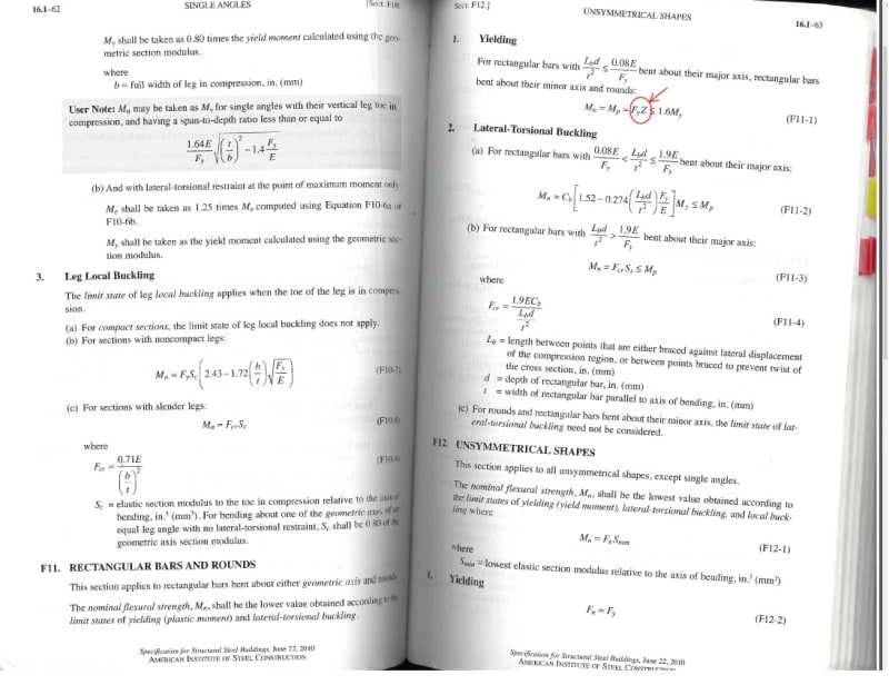
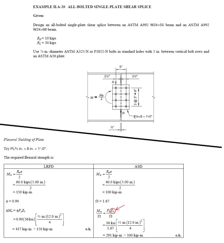
In the below extracts from AISC manual and examples, why is the Plastic section modulus (Z=bd2/4) used for evaluation. Shouldn't this be the Elastic section modulus (S=bd2/6)?

Untitled_fldbsk.jpg


Untitled2_msmzs5.jpg
 
...is it a valid assumption (as @milkshakelake pointed out) that if the moment exceeds the yield capacity of the web-plate, it will develop a plastic hinge and the connection will behave as a shear connection?

As long as the ultimate tensile capacity on the net section (through the bolt holes) is greater than the yield capacity of the gross section, for both the girder web and the splice plates, I think that assumption would be valid. Otherwise, to validate that assumption, you would need to do an analysis of the strains in the plates to ensure that fracture of the splice plates or web due to the rotation at the splice is not the controlling failure mode. Most likely, it is not, but I wouldn't put my stamp on a rating without checking it.

Rod Smith, P.E., The artist formerly known as HotRod10
 
In the below extracts from AISC manual and examples, why is the Plastic section modulus (Z=bd2/4) used for evaluation. Shouldn't this be the Elastic section modulus (S=bd2/6)?

It assumes full yielding of the splice plates is allowed, which is a valid assumption, if the bolts are fully tensioned (slip-critical connection). With the bolts fully tensioned, yielding will occur first on the gross section of the splice plates, beginning near the centerline of the splice, and a ductile plastic hinge will form.

In your case, since the bolts are in bearing, yielding would occur first along a line through the bolt holes, and if the steel there reaches its ultimate tensile strength before yielding occurs elsewhere, further rotation may cause excessive strain and fracture of the splice plates.

You can use Z, but it would need to be the Z of the net section through the bolt holes. That would be compared to Fy*S for the gross section, to determine whether the failure mode would be ductile or brittle.

Rod Smith, P.E., The artist formerly known as HotRod10
 
@BridgeSmith: I checked that for one of the splices and the Flexural rupture strength of the plate/beam web (through the bolt holes) is higher (6%) than the Flexural yield strength at gross section of the plate. This is using Elastic section modulus (S) for the evaluation of Flexural yield strength at gross section.

Thank you for the clarification of the connection behavior. I agree that for full yielding of the plate to occur at the gross section, all other connection component capacities must be higher to avoid yielding elsewhere.
However the AISC equation reference I mentioned above which is also referred in AASHTO LRFD 6.12.2.2.7-1 uses Z without indicating any such criteria (Edit: realized that these refer to a general rectangular plate so not specifically at a bolted connection, however the limit is still Mn=Mp=fy*Z < 1.6fy*S and not Mn=fy*S). I have also attached the AISC example. It is not a slip-critical connection and the Flexure rupture capacity at net section is less than flexural yielding at gross section. Still the Flexural yielding at gross section calculation uses Z and not S.
 
 https://files.engineering.com/getfile.aspx?folder=798b3143-f112-4523-91bf-ce2ce1e6d893&file=AISC_Splice_Rating_Example.pdf
Status
Not open for further replies.

Part and Inventory Search

Sponsor