Eng-Tips is the largest engineering community on the Internet

Intelligent Work Forums for Engineering Professionals

Bolted Web Splice Joint behavior 1

Status
Not open for further replies.

AK4S

Structural
Jan 2, 2015
98
0
0
US
I am involved in a discussion regarding the behavior of a Bolted Web Splice Joint and looking for some clarity to understand the true behavior of the connection.
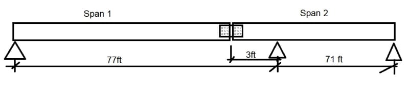
In an existing bridge(several simple spans), one of supports appears to have been constructed incorrectly (shifted by 3ft, whereas all other spans are of the same length). So a Bolted Web Splice Joint is observed in the beams of this span (span1).
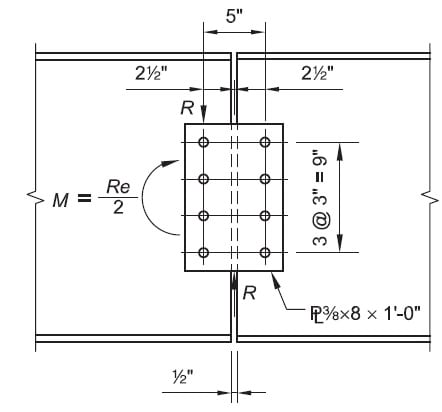
Untitled_o0wrap.jpg

Splice detail:
Web_Splice_Sketch_apfiya.jpg

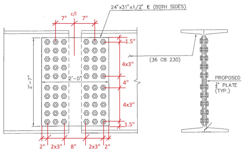
As seen above, there is discontinuity at the top & bottom flanges and the concrete deck above is also discontinuous at this location (expansion joint in deck directly above this splice). Hence it is my understanding that this connection is primarily a shear connection would resist shear and the resultant moment caused by eccentricity of the shear load.
i.e. The span 1 is equivalent of a hung span and the splice connection was never intended to take moment, i.e. the beams were not continuous.

The argument I have received from a colleague is that due to the size of the connection, the rotation of the beams is restricted and hence the behavior will be more like a "partial" moment connection with the system behaving like a 2span continuous beam and the web-splice plate carrying/transferring the bending moment at this location.

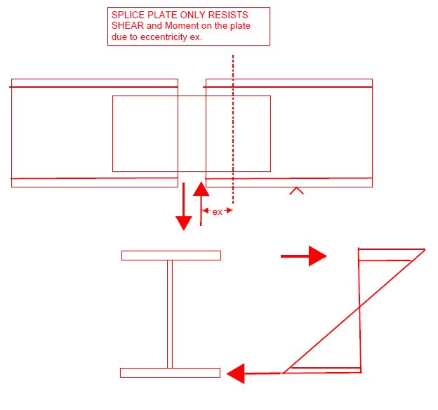
I do not agree and feel that flange-splice plates are required to transfer the moment at this connection and a web-splice plate only is not adequate. So I would model the two spans with a "hinge" at the splice location.
Bending moments are primarily transferred through flange splice plates and moment transfer through web portion is not significant. See sketch below:
Untitled2_pqwq4d.jpg


[ul]
[li]Does the behavior change when you have a connection with so many bolts? Like the bolted connections are locked in with dead load and during live load the beam rotation is prevented thus transferring moment through the web-splice connection?[/li] I can understand this may not be a "pure Hinge" condition, But the moment transfer should not be significant to specifically check the web-splice plate to carry it and if so, what is the expected bending moment? carrying full moment through the connection is not valid. Any thoughts?
[/ul]
 
Replies continue below

Recommended for you

However the AISC equation reference I mentioned above which is also referred in AASHTO LRFD 6.12.2.2.7-1 uses Z without indicating any such criteria (Edit: realized that these refer to a general rectangular plate so not specifically at a bolted connection,

Which edition if the AASHTO spec are you using? In the 9th edition, that equation is for "Rectangular Bars and Solid Rounds", so it's not even applicable to plates, even ones without holes. The only other part of Article 6 that I could find that references the plastic section modulus is in 6.12.2.2.2, which deals specifically with steel box-shaped sections, such a box or tub girders.


Rod Smith, P.E., The artist formerly known as HotRod10
 
Checking the flexural capacity using the Elastic Section Modulus, S, tells you when the edge of the plate begins to yield. Checking the flexural capacity using the Plastic Section Modulus, Z, tells you when the entire depth of the plate has yielded.

AISC allows you to use to use Fy*Z instead of Fy*S for the flexural capacity since that is the point where additional load no longer results in any additional resistance (even though for moments beyond Fy*S the amount of resistance to rotation begins to be less than what is predicted by using EI).

When a moment is applied to the splice plate, the edges of the plate at the bolts will begin to yield first since Snet is reduced there. Then, since you already checked that Fy*S is less than Fu*Znet, the plate will then begin to yield at the region that has not been reduced by bolt holes. This is the point where a plastic hinge will start to form (meaning that the flexural rigidity is now less than EI). Now what you haven't confirmed yet is if a full plastic hinge can form (meaning that EI is 0). For this to be possible, Fy*Z must be less than Fu*Znet, otherwise the plate will rupture at the bolt holes before the full plastic hinge forms. This ends up just being a check that Z/Znet < Fu/Fy.

As others have mentioned, the splice plate will be a partially restrained moment connection. Analyzing the beams using a hinge is a conservative way to make sure that the beam to the left of the hinge has sufficient flexural capacity, and that the deflection criteria is met, but it will not be the true behavior of the system. The actual behavior will behave more closely to the model of a moment connection at loads up to where the splice plate reaches Fy*S. (In reality there is a reduced stiffness at the splice plate due to its reduced cross section and movement in the bolts, but this is a 14" segment in a 77 ft long beam so it is unlikely to have too big of an effect.) At moments beyond Fy*S, the stiffness will begin to be reduced at the splice plate, up until Fy*Z is reached (assuming the plate does not rupture as discussed above). Beyond this point, any additional load will get distributed similar to the model with a hinge.


Structural Engineering Software: Structural Engineering Videos:
 
@ProgrammingPE: Thank you for the detailed explanation of the AISC equation and the reasons for using Z vs S.
I made a mistake in my earlier calc, so the % difference is larger. Have Checked that:
[ul]
[li] Fy*S < Fu*Znet. Indicates plate will begin to yield at the gross section at the middle of the splice (without bolt holes) before the rupture at the bolt hole section [/li]
[/ul]
[ul]
[li] Fy*Z < Fu*Znet. Indicates that the plate will continue to yield till the full plastic hinge forms and this will happen before the rupture at the bolt hole section [/li]
[/ul]

Now, I am trying to figure out how I can present the results. I am rating this existing bridge. Generally if it was a regular splice (with top & bottom plates), then the state DOT guidelines does not require one to rate the splice unless the deteriorated condition of the components would require a review.
This is not a regular splice and I have these splices at same position on different beams at various levels of deterioration in the web-splice plate. So I see the following cases happening:
[ul]
[li]For a combination of some truck load condition and a less deteriorated web-plate, the moment (without hinge case) at the splice will be < Fy*S[/li]
[/ul]
[ul]
[li]For a combination of some truck load condition and a more deteriorated web-plate, the moment (without hinge case) at the splice will be > Fy*S but < Fy*Z[/li]
[/ul]
[ul]
[li]For a combination of some truck load condition and a more deteriorated web-plate, the moment (without hinge case) at the splice will be > Fy*Z. So a plastic hinge is formed and now the splice connection behavior becomes like a Shear connection[/li]
[/ul]
So for rating the Bridge, can't I take the simpler and conservative route and assume that the splice connection will not govern the bridge rating since when the loads are exceeded, the splice connection will form a plastic hinge and resulting rating of this shear connection (using only shear+resultant moment caused by eccentricity) is quite high (>15).

For the beams, it is ok to rate them considering a hinge at the splice location as this is the more conservative approach.

@BridgeSmith: Can you direct me to the AASHTO section which would be applicable in this case for the web plate? For the rectangular bars section AISC and AASHTO have the same equation using Z.
 
@BridgeSmith: Can you direct me to the AASHTO section which would be applicable in this case for the web plate?

I don't think there is one. The closest analogous provisions would be for checking the flange splice plates, where the tension on the splice plate is limited to force that yields the gross section or fractures the net section, whichever is less (with the proper resistance factors applied (from 6.5.4.2). To relate that to the web splice, you'd calculate the moment capacity of the gross section at first yield and the moment capacity at rupture (fracture) on the net section, take the smallest of the 2, and use that as the capacity in your rating calculations.

Rod Smith, P.E., The artist formerly known as HotRod10
 
AK4S:
For all of the F[sub]y[/sub]*S’s, F[sub]y[/sub]*Z’s and F[sub]u[/sub]*Z[sub]net[/sub]’s floating around in this discussion, don’t forget that the idea of a plastic hinge forming contemplates a member which is sufficiently stiff in its parts (compact, etc.) so that the hinge can form without the member buckling locally near the hinge. Then, S, Z and Z[sub]net[/sub] should also consider the .5" pls. corroded to whatever extent they might be, and that the edges of those plates might look something like a crossbuck saw blade and not a nice rolled mill edge. I don’t think I would want to push those pls. or the pl. edges to anything even near F[sub]u[/sub]*Z[sub]net[/sub], and probably not even too near F[sub]y[/sub]*S[sub]net[/sub].
 
@BridgeSmith:
I am referring back to AASHTO LRFD Equation 6.12.2.2.7-1 for "Rectangular Bars and Solid Rounds" and trying to understand why this section is not applicable to the web splice plate.
Per my understanding, this section is still applicable for plates, except that for the web splice plate the section depth > width, hence LTB will govern compare to yielding as mentioned in the section commentary.

AaSHTo_xvcfn3.jpg


This appears to be similar to the AISC section F11 which I have referred in my earlier response.

AISC_n7sgnl.jpg
 
@dhengr: Thank you for the caution. I understand for the deteriorated plates especially with the rough edges or 100% loss at edges can cause a failure to happen before the theoretical computed capacities.
Will review it closely once I confirm my approach and get to evaluating each plate.
 
AK4S,

Yes, you still need to check the LTB for the splice plate. Based on the dimensions provided in your original post, assuming Lb is 8", and grade 36 plate, I come up with a Lb*d/t2 ratio of ~ 992, which puts each plate firmly in the "LTB will control the nominal moment capacity" camp.

Please note that is a "v" (as in Violin) not a "y".
 
@winelandv: Thank you for the calculation. Yes, LTB controls. I was conservatively using Lb=7.06" (clear distance between bolt holes)
 
I don't see how a bolted web splice plate can fail in LTB. Straight flexural buckling, maybe, but not torsional buckling.

Anyway, Section 6.12.2.2.7 may be applicable for plates (IMHO, I don't think so, since width is greater than the flexural bending length), but the holes in it changes things considerably. The applicable provisions, if anything in AASHTO is applicable, would be the provisions for bolted connections, and plates with holes where the capacity is calculated.

The AASHTO provisions aside, theoretically, you could use Z in your capacity calculations, but you'd have to calculate Z at the critical section, which would be the net section passing through the bolt holes.

Btw, there's also the failure mode of block shear rupture (6.13.4) that should be considered.

Rod Smith, P.E., The artist formerly known as HotRod10
 
@BridgeSmith:
I think I am considering all the required provisions:
[ul]
[li](1)bolt shear/bolt bearing to calculate the capacity of the bolt group[/li]
[/ul][ul]
[li](2)Flexural yielding of the plate at the gross section (middle portion without holes)-conservatively using S or using Z Per Eq 6.12.2.2.7-1(upper limit before plastic state) including check for LTB per Eq.6.12.2.2.7-2[/li]
[/ul]
[ul]
[li](3) Flexural rupture of the plate at the net section (portion with bolt holes)-I could not find an AASHTO reference for this evaluation, but I am evaluating it similar to AISC provisions[/li]
[/ul]
[ul]
[li](4)Shear Yielding of plate for gross section[/li]
[/ul]
[ul]
[li](5) Shear Rupture for net section at bolt holes[/li]
[/ul]
[ul]
[li](6) Block shear rupture per 6.13.4 with Ubs =0.5[/li]
[/ul]
 
Calculating the flexural yielding of the plates using would give you a capacity higher than what you should get for the flexural capacity at the section through the bolts. If it doesn't, you're not calculating the flexural capacity at the first row of bolts correctly, since there's no way that the plastic flexural capacity of the net section with holes should exceed the plastic flexural capacity of the gross section without holes.

I say that using the plastic moment capacity for the section at the bolts holes may overestimate the rupture strength, if the rotation is not limited to a value where the ultimate tensile strain at the edges of the splice plates is below the strain where it could fracture. My guess is that it is, but I wouldn't hang my hat, or my PE stamp, on that assumption.

If it was me doing the rating, given all of the behavioral unknowns and lack of clear guidance from the spec, I would limit the usable flexural capacity of the splice plates to Fy * Znet at the bolt holes, or Fy * Sgross, whichever is lower.

Rod Smith, P.E., The artist formerly known as HotRod10
 
Jumping in late here as I have only just joined. From my perspective it is the engineer who wants the connection to behave in a simplified way so that flange plates carry the moment and web plates the shear. Connections never behave the way you want or expect. The only true hinge connection is a single pin/bolt after that they all carry some moment - fully fixed is another definition open for interpretation.

You could try modelling the connection in something like IDEA StatiCa or ANSYS to get the connection results and capacity. You would need to know forces for the former not necessarily for the latter. You would then understand how the connection behaves under load.
 
@BridgeSmith ... I thought the same, but he's doing a yield analysis on the gross section and a rupture analysis on the net section. why? IDK

"Hoffen wir mal, dass alles gut geht !"
General Paulus, Nov 1942, outside Stalingrad after the launch of Operation Uranus.
 
If you are working on a bridge you may have no choice in regards to adding the flange splice plates. Most DOT's in the US require it regardless of what your calculations show. Also, if you read some steel design books they often comment on not having the flange plates changing the "stiffness" of the member and you may inadvertently create a "weak spot". If this project involves a government agency you may want to reach out to ask if what you are proposing is even allowed.
 
rb1957 said:
@BridgeSmith ... I thought the same, but he's doing a yield analysis on the gross section and a rupture analysis on the net section. why? IDK

That is, I believe, the proper way to check the capacity of the splice plates, per the limited applicable provisions in the AASHTO spec, and essentially what I was suggesting. I don't take issue with that part of the approach. However, because of the uncertainty in the level of rotational (moment) resistance offered by the splice, I think it should be treated as a hinge point when checking capacity vs. demand and calculating rating factors for the rest of the girder.

Rod Smith, P.E., The artist formerly known as HotRod10
 
@TheRick109, this is an existing bridge that is being evaluated/rated, but your point is valid, nonetheless. We, at my DOT, would not have approved that 'fix' on a bridge that was to be open to the public, and if we saw that configuration on a bridge, it would most likely be closed until proper splices were installed.

Rod Smith, P.E., The artist formerly known as HotRod10
 
@BridgeSmith:
For the worst case with plate thickness b=0.35", depth d=31"
Elastic section modulus (S=bd^2/6) = 56.0in3
Plastic section modulus (Z=bd^2/4)= 84.1in3
Net Plastic section modulus at bolt hole (Ref. AISC Eg 15-5 in snapshot below),Znet = 52.5in3

The allowable stresses for Inventory condition per Manual of bridge evaluation for 33ksi material:
[ul]
[li]For Flexural yielding =0.55Fy=18ksi[/li]
[/ul]
[ul]
[li]For Flexural rupture =0.5Fu=30ksi[/li]
[/ul]

So, the calculated flexural capacity:
[ul]
[li]For Flexural yielding @ Gross section using S =18ksi*56in3=1008k-in[/li]
[/ul]
[ul]
[li]For Flexural yielding @ Gross section using Z =18ksi*84.1in3=1513k-in[/li]
[/ul]
[ul]
[li]For Flexural rupture @ Net section using Znet =30ksi*52.5in3=1575k-in[/li]
[/ul]

MBE does not seem to provide a separate allowable stress associated with Plastic limit, but how is it different from the AISC example I have shared earlier (see snapshots below):

Untitled_piszyu.jpg

Pages_from_AISC_Splice_Rating_Example_dl2hu4.jpg
 
@BridgeSmith: No disagreement with your response that to rate the rest of the girder, the splice connection is to be treated as a hinge point.
 
why wouldn't you add cap splice straps ? (to restore the original strength to the beam) ?

Sure, you can do calcs that show "everything's fine" but ... I (and others by the sound of it) don't like this minimal approach. An error has been made, and the repair should restore the strength of the original. Else you need to reanalyze the entire bridge.

"Hoffen wir mal, dass alles gut geht !"
General Paulus, Nov 1942, outside Stalingrad after the launch of Operation Uranus.
 
Status
Not open for further replies.
Back
Top