Eng-Tips is the largest engineering community on the Internet

Intelligent Work Forums for Engineering Professionals

  • Congratulations waross on being selected by the Tek-Tips community for having the most helpful posts in the forums last week. Way to Go!

Boundary condition to allow nodes to move in parallel?

Status
Not open for further replies.

dfgsdfgfd

Mechanical
Sep 30, 2015
37
0
0
US
Hello everyone,

I have a structure, where I want to constrain the nodes on one surface in X direction such that they are allowed to move, but only in parallel. Or, in other words, all nodes on the surface must move the same distance, if there's movement going on.

There certainly are some workarounds, but is there a simple way to model this? I tried using a (kinematic) coupling-constraint, where I create a reference point on the surface as a reference, but it's slow and has problems to converge. I'm using ABaqus 6.14, static, general.

Thank you very much!

temp1_mneuit.png

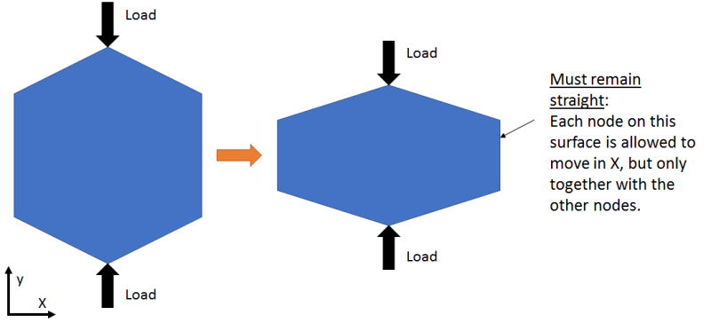
(please note that I'm using a 3D model -- the picture is a 2D representation only)
 
Replies continue below

Recommended for you

Kinematic coupling should work - when used correct.

Another option is an Equation. Place one node of that surface in a set. Place the other nodes in a second set. Create the Equation between the sets.
Abaqus Uses Manual 35.2.1 Linear constraint equations

A MPC would be a third option.
 
Thanks very much for the quick response.

When I add kinematic coupling, the simulation doesn't converge anymore:

console said:
The job input file "JOBNAME.inp" has been submitted for analysis.
Job JOBNAME: Analysis Input File Processor completed successfully.
Error in job JOBNAME: Too many attempts made for this increment
Error in job JOBNAME: THE ANALYSIS HAS BEEN TERMINATED DUE TO PREVIOUS ERRORS. ALL OUTPUT REQUESTS HAVE BEEN WRITTEN FOR THE LAST CONVERGED INCREMENT.
Job JOBNAME: Abaqus/Standard aborted due to errors.
Error in job JOBNAME: Abaqus/Standard Analysis exited with an error - Please see the message file for possible error messages if the file exists.
Job jJOBNAME aborted due to errors.

Here's what I do:
1. Create reference point outside the structure
2. Constraints -> Create Constraint -> Coupling
3. Select the Reference Point
4. Choose "Surface" and select the respective surface
5. In the "Edit Constraints" windows that appears, I select "Coupling Type" Kinematic, "Constrained Degrees of Freedom" U1, UR2, UR3, "Influence Radius" To outermost point on the region. All other options are unchecked.
6. I don't have any other constraints on the Reference Point or on the surface used.

Without adding the constraint, everything converges and the simulation finishes successfully.
 
When you connect only some DOF, then the Refnode is not connected to the structure in the other DOF and will move free, which is bad in a static analysis. Add springs or BC in those DOF at the Refnode.
 
Thank you very much. I now used the proposed solution with the equation, which works like a charm.
It's also good to know about the first solution with the kinematic coupling. Thanks!
 
Maybe I'm missing something, but doesn't this model exhibit quarter symmetry? You could model one quarter and just use appropriate boundary conditions?
 
You're missing the point of the question. What I show is only an example to demonstrate the problem. SYmmetries wouldn't make any difference. Mustaine3 already fully answered my question.

 
Status
Not open for further replies.
Back
Top