Eng-Tips is the largest engineering community on the Internet

Intelligent Work Forums for Engineering Professionals

Boundary conditions for simply supported beam FEA

Status
Not open for further replies.

MatthewLynch

Mechanical
May 27, 2024
10
0
0
AR
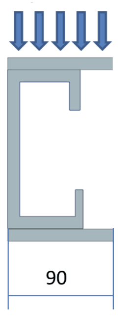
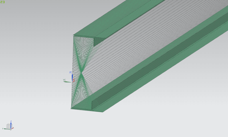
Hello, I am trying to model a simply supported beam with a distributed load. The beam is formed with a C section channel and two plates that are welded, one on top and one on the bottom. To model this I am using NX and using CQUAD4 elements and have done a 1D connection Edge to Edge with RBE2 joining the plates to the C section channel.

Now I am trying to model the pin and roller for the simply supported beam. For this I have placed a point in the CG of the section at each end and I am connecting the point to the edges with RBE2 elements. The idea of this is to be able to allow it to rotate maintaining it flat.


Beam_eeqwkm.png


Now when I analyze my results they do not look as I expect.

Here is an image of the stress on XX

XX_pgyi1o.png


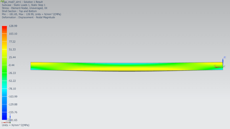
For a simply supported beam I would expect compression on the top and tracction on the bottom, as seen in te center. But we can see that this does not happen at the supports. There I am getting traction on top and compression on the bottom. So it is not working as a simple supported beam.

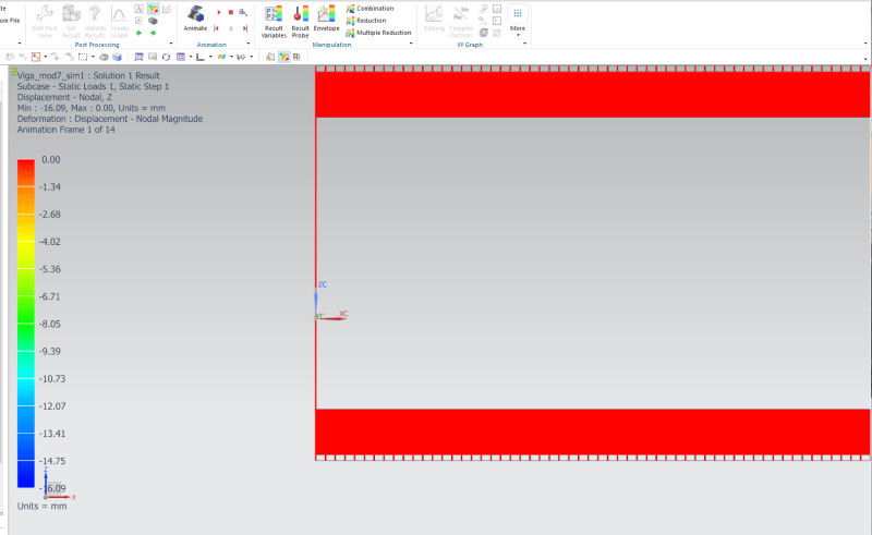
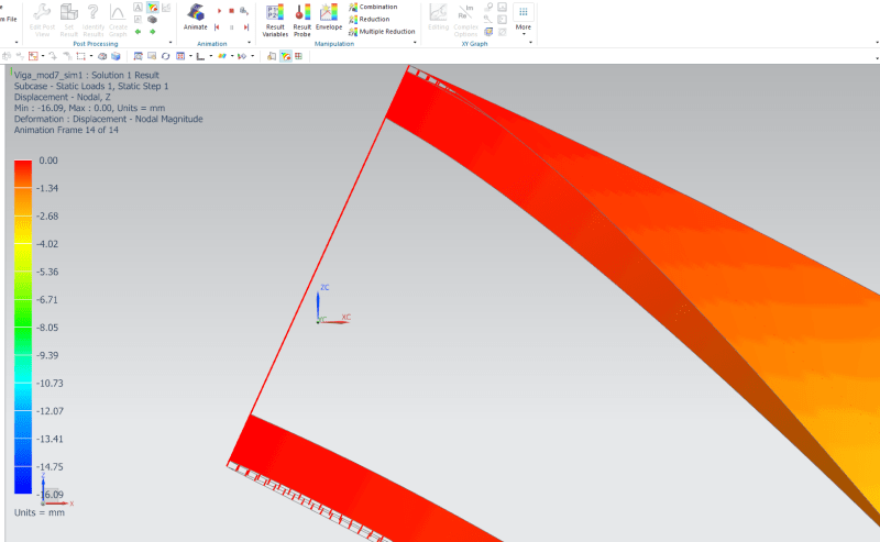
If I look in detal the Z displacements of the edge I can see that the face of the beam rotates, but there is no displacement in Z. So I guess that it is expanding then?

I have placed it at the top to have a reference on hight and see that there is no displacement in Z direction.

Desplazamientos_Z_1_peaaks.png


Desplazamientos_Z_2_tvnc6n.png


What am I doing wrong? what would be the best way to model a simply supported beam? Do I have to release some of the DOF's on the RBE2? What DOF should I release in that case? I do not fully understand how the DOF releasing on RBE2 elements works.

Thank you
 
Replies continue below

Recommended for you

How are you applying loads?

And get rid of the RBEs between the plates and C channel flanges and just merge the common nodes. RBEs are nothing but trouble and often are unrealistic (there is no such thing as "infinite stiffness" in the real world).
 
The loads are applied distributed on the surface of the top plate.

The reason for using the RBE2 is that there are no common nodes. I started from a 3D model and got the midsurface and I am meshing thet. So the distance between the C channel and the plates y 3mm. I guess I could replace them for CBAR elements and maybe just do a x10 to the young module to make it more rigid. But not sure how that would affect the no displacement in Z direction on the boundary condition.
 
I would just move the plates to the position of the flanges and merge the nodes. Close enough at least for a starting model to sort out the rest of it. As I said, in my long experience, RBEs are nothing but trouble and I try to avoid them as much as possible.

Be sure you have only fixed X at one end of the beam and not both.
 
I will try, but my professor did not really like when I juggested moving the plates. And this is why I went the route of RBE2 elements.

What would you use to represent the simply support? would you use the RBE2 to a point in CG or would you do something else?
 
Sorry to be blunt, but does your prof have any clue? Any experience with FE modelling? I have done it off and on since the early 1980's, starting in the days of mainframes and having to write Fortran code to generate models before the days of fancy pre/post processors. Ugh we've come a long way.

I would just move the plates and merge the nodes and get the model running ok with good results with that. Then move to something more complicated if really needed.

Yes, at the ends you don't have much choice but to use an RBE2 between the beam ends and a single point at the CG (well it would be better to be at the Shear Center that way you won't get twisting when applying a vertical shear load). Just be careful about what boundary conditions to use at the ends (fix 123 at one end, 23 at the other end).
 
SWComposites said:
Sorry to be blunt, but does your prof have any clue? Any experience with FE modelling? I have done it off and on since the early 1980's, starting in the days of mainframes and having to write Fortran code to generate models before the days of fancy pre/post processors. Ugh we've come a long way.

I would just move the plates and merge the nodes and get the model running ok with good results with that. Then move to something more complicated if really needed.

Yes, at the ends you don't have much choice but to use an RBE2 between the beam ends and a single point at the CG (well it would be better to be at the Shear Center that way you won't get twisting when applying a vertical shear load). Just be careful about what boundary conditions to use at the ends (fix 123 at one end, 23 at the other end).

Hi. This is my last final exam to get my engineering degree. I have had some difference of oppinion on how to approach the proble with my professor. But at the end of the day, it will be him evaluating and the one that decides if I graduate or not. I can anyway try a model with the FEM moved so that I can merge the nodes and try and compare results. After all, they are 3mm thick, that is not going to make a huge difference to results.
I am also the person you were helping with modeling some spot welds a few days ago. So instead of modeling the beam again with the plate moved I added the RBE2 spider to the beam that is not welded all along the length and has instead the spot welds (so I wouldn't have the problem with the RBE2 elements representing the weld) and I still see the same behavior on my supports where the face of the beam rotates but there is no displacement in Z on the top and bottom, as if the face of the beam would be streaching.

GregLocock said:
You can also check your results (stress and deflection)against a handcalc. It won't be exact as Sparweb says because you aren't supporting it at the shear center.

I have done some handcalc of a more simplified beam in geometry to compare some stress values and at the center of the beam there is little differende with stress. But at the supports, being a simply supported beam I should only have shear stress and not bending. And specialy bending with traction on top and compression on bottom. I do not know if this is happening due to this stretching of the face that I think is happening or there is some other type of restriction I can't notice that doesn't allow it to rotate freely.
 
As an update. To make it as simple as possible I have modeled only a C section channel with the hight of the C channel and the width of the plates. This way it is easier to do some handcalc and compare. I have also placed a point load and mid length and on the share center (or at least tried, the beam is still getting some torsion). To place the point load I put a point in the share center location and with RBE3 elements point to edge connected the hole C section.
For the supports I again created a point in the CG and connected with RBE2 elements point to edge. I still see this behaviour that the face will rotate but there are no displacements in vertical direction. And I also still get some "inverted" bending stress at the supports. I don't understand what is going on here
 
your RBE at the ends ... how are you constraining the central node ? You've posted a bunch of pictures that look to come from different runs, maybe ? Your model is acting as though it has fixed ends (the only reason bending moments flip along the beam).

if you are going to the trouble of loading at the shear center, ...
1) do it properly, calc the shear center (it ain't hard),
2) ensure that your end supports are in line with this point.

What type of RBE are you using ? one type (RBE2?, rigid) will force the section to keep it's shape (which may be affecting your results); the other type (RBE3?) adds no stiffness to the model (and may be what you want).

Can you please check your typing ... "shear" not share".

If you're playing with this, why not model a cantilever, see if that works better for you ? In any case, you could say you've modelled 1/2 the beam ...


"Hoffen wir mal, dass alles gut geht !"
General Paulus, Nov 1942, outside Stalingrad after the launch of Operation Uranus.
 
Ok, I went over my math and I had made a mistake. That is why my shear center was off and was still getting some torsion. Now applying a point load at midlength of the beam and and my supports also with RBE2 elements on a point in line with the shear center I am getting correct stresses. I still see no displacement in the Z direction on the face rotation, but this displacement is also very little, so shouldn't affect results much.

I am now back to my C channel with plates welded on top and bottom. Sorry, I do not always understand english all that well, so I will try to reply the best I can.

rb1957 said:
your RBE at the ends ... how are you constraining the central node ? You've posted a bunch of pictures that look to come from different runs, maybe ? Your model is acting as though it has fixed ends (the only reason bending moments flip along the beam).

What I did was create a point at the CG. Frome there I made a 1D connection of type Point to Edge going from the central point to the edges of the beam. That is what I am trying to show in the first image. The RBE2 elements on their dependant node have all 6 DOF's on.

Now, having my supports in line with the shear center is only valid for when my load is also on the shear center, correct? or is it incorrect that when I have a distributed load on the surface of the top plate I put my supports in line with the CG?
This is what I am trying to model, with the load distributed over all the top surface (distributed both in width and in the length of the beam).
Seccion_viga_ialcye.png


Would it be correct to use RBE3 for that? it was my understanding that I should not put a boundary condition that restricts displacement in 3 axis on a RBE3 dependant node.
 
if your load is at the shear center, and your reactions are at the centroid, then there will be some torque appearing at the reactions. If you want simple shear at the reactions, then support the beam at the shear center.

Ok, your RBE as all dependent freedoms on. What are you constraining at this node ? all 6 dof is a built-in support, 3 (linear) dof is a pinned joint. Pureists will argue that you need to constrain only one axial freedom, sure, ok. But in any case, the model won't run.

Because why ? Your constraints need to react all 6 dof, even if they aren't active, to keep the math demons in the FEA machine happy. The XYZ constrained at one end, and YZ at the other, you still need to constrain RX at one end. And check that this constraint isn't reacting any load (it shouldn't).

But if your load is at the shear center, and the constraints at the centroid, then there will be some torque produced, and this should be constrained at both ends.

I personally don't like the way you're being taught. You are micromeshing models without understanding (IMHO) how models need to be constrained. I would have you starting with stick models, but I'm an olde and crotchety curmudgeon.

"Hoffen wir mal, dass alles gut geht !"
General Paulus, Nov 1942, outside Stalingrad after the launch of Operation Uranus.
 
ok, not sure what the goal of the model is (other than getting your degree); is it to demonstrate how to simulate a simply supported beam? get "correct" displacements and/or stresses? or something else. and not sure which configuration, C + plates or C only, point load or distributed load, you need to analyze. as with anything in engineering, its best to clearly and fully define the problem before diving in.

not sure exactly where you are with this, but I'm going to outline how I would sort all this out, starting with something simple and adding more complexity step by step.

step 1
start with the C channel only model. remove all boundary conditions and rigid elements. At one end, fix all nodes in 123, and at the other end fix all nodes in 23. yes, this is fixed ends, not simple supports, but bear with me. Now apply a vertical load at a single node at the beam lengthwise center directly above the web centerline. run and get displacements and stresses. there should be a vertical displacement. check this vs a hand calc using beam equations (Roark, or online, or something). make a deformed geometry plot of the displacement (do not use contour plots for displacements, they are just confusing at best, and rarely useful).

step 2
remove the boundary conditions at the ends. create a node at each end at the shear center location. create an RBE2 element at each end from the shear center node to all of the nodes at the ends. the shear center node is the independent node on the RBE. all other nodes are dependent nodes and should be connected in 123 only. apply a boundary condition constraint to the shear center nodes, fix 123456 at one end, fix 23456 at the other end. this is still a fixed end condition. leave the single point load in the middle. run and compare displacements to step 1 and hand calc.

step 3
revise the shear center node boundary conditions, fix 1234 at one end, fix 234 at the other end. this is freeing up rotation about Y and Z to simulate a simple support condition. run and get displacements and stresses. check the vertical displacement against a simple supported beam hand calc. should be close.

step 4
remove the single point load at the center. create a node a the shear center in the center of the length of the beam. create an RBE2 element from the shear center node to all of the nodes at the center cross section of the beam . the shear center node is the independent node on the RBE. all other nodes are dependent nodes and should be connected in 3 only. apply vertical load to the shear center (independent) node. run and compare to results from step 3. should be similar.

step 4a
for comparison, replace the RBE2 at the beam center with an RBE3, connected the same way. run and compare to step 4. should be similar but will have less constrain on the cross section compared to step 4.

step 5
if you need to analyze a distributed load applied to the upper flange, go back the step 3 and remove the point load and replace with a distributed load over the C channel upper flange. run and compare displacements to a hand calc.

not sure what else you need to do, and if you need more help, so run thru the above and provide a results summary.

 
Status
Not open for further replies.
Back
Top