Continue to Site

Eng-Tips is the largest engineering community on the Internet

Intelligent Work Forums for Engineering Professionals

  • Congratulations pierreick on being selected by the Eng-Tips community for having the most helpful posts in the forums last week. Way to Go!

Braced Excavation Design in New York City

Status
Not open for further replies.

mole20

Civil/Environmental
Feb 8, 2022
4
Loading_Diagram_pqttbb.png


Hello everyone,

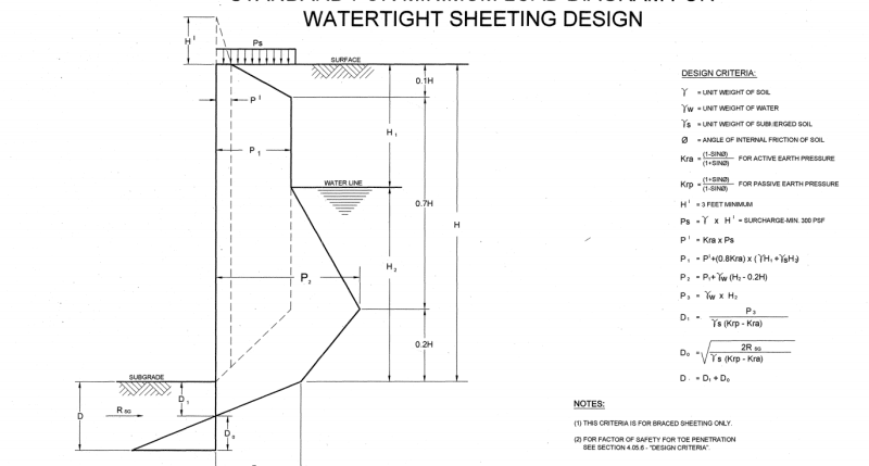
I'm working on a braced excavation design in NYC. The contractor wants to utilize sheet piles with three levels of wales and corner braces. This is my first job in NYC that requires watertight sheeting and as I understand it should be designed in accordance with the DEP Loading Diagram (attached). I'm a little confused as to how the reaction at subgrade is calculated?

Any suggestions would be greatly appreciated.
 
Replies continue below

Recommended for you

It's a system of equations. You know everything above the subgrade level based on the geometry of the excavation and soil properties. So then you have to solve the system of equations (D1, D2, and D) to find Rsg.
 
[ol 1]
[li]Draw separate pressure diagrams for the earth pressure, water pressure, and surcharge pressure.[/li]
[li]Calculate the trapezoidal pressure diagram above subgrade for the retained, stratified(?) soil(s) considering the relative amounts of moist and buoyant soils.[/li]
[li]If you do not know how to derive the trapezoidal earth pressure diagram for stratified soils with a water table, you should not be designing this wall.[/li]
[li]I recommend that you read AASHTO's Bridge Design Manual section on anchored walls.[/li]
[li]Calculate the theoretical soil pressure acting on the wall below subgrade, considering the retained soils as a surcharge on the soils below subgrade.[/li]
[li]Chose elevations for your 3 braced wale levels - A, B, and C.[/li]
[li]Cut the wall and the pressure diagrams at Level B and Level C.[/li]
[li]Label the B level reaction as B1 for the upper section diagram and B2 for the middle section diagram.[/li]
[li]Label the C level reaction as C1 for the middle section diagram and C2 for the lower section diagram.[/li]
[li]The lower diagram should include the driving pressures below subgrade and the passive pressure in front of the SSP wall.[/li]
[li]Take the upper diagram section and take moments about B1 to find A reaction.[/li]
[li]Sum the forces in the upper diagram to calculate B1 reaction.[/li]
[li]Calculate the cantilevered and interior moments for the upper wall section.[/li]
[li]Repeat this process for the middle section.[/li]
[li]Calculate B2 and C1. B = B1 + B2.[/li]
[li]Calculate the interior moment in the middle section.[/li]
[li]Label the SSP embedment depth as D (an unknown) with the pressure diagrams applied to the appropriate sides of the SSP toe.[/li]
[li]The driving pressure moment for D embedment must equal the resisting moment for D embedment.[/li]
[li]Take moments about C2 and solve for D with moment equilibrium.[/li]
[li]Knowing D, sum forces in the lower wall section from C2 to the SSP tip with D embedment. Driving forces - resisting forces = C2.[/li]
[li]C1 + C2 = C.[/li]
[li]Find point of zero shear in a wall section. Maximum moment in any wall section occurs at the point of 0 shear in that section.[/li]
[li]Now you know the three level reactions and the moments in all three partial wall sections - top, middle, and bottom with embedment.[/li]
[li]Chose a SSP size that can resist the maximum bending moment.[/li]
[li]Increase D calculated for moment equilibrium by at least 20% as a safety factor on the passive resistance.[/li]
[/ol]
This process is shown in many reference books. If you don't understand the above steps, you should not be designing this wall.
I recommend that you read AASHTO's Bridge Design Manual section on anchored walls.

 
Status
Not open for further replies.

Part and Inventory Search

Sponsor