Eng-Tips is the largest engineering community on the Internet

Intelligent Work Forums for Engineering Professionals

Braced Frame K factor Question`

Status
Not open for further replies.

zrck99

Structural
Dec 19, 2014
82
0
0
US
Hello all,

I am designing a 45' tall x 20' wide braced frame shown in the attached pdf. It consists of two knee braced frames above a tension only x brace. I'm hoping that someone can either confirm my assumptions for k factors or point me in the right direction for correcting them. My columns will be continuous from the ground to the top of the full frame. Each beam and brace member is hinged at each end.

My understanding is that at the x brace, we can use a k = 1 for the beam and column because this frame is non sway so worst case k = 1 and by running the column on up past the x brace level, we would be adding some fixity and the resulting k would be reduced from 1.0 some.

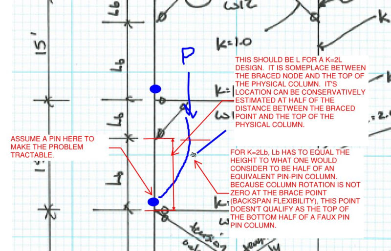
When I have modeled single story knee braces in the past, I've considered the bottom of the column to be a pin and the upper brace to create fixity resulting in a k = 2.0 and unbraced length = the height from the ground to the knee brace work point or the distance from the knee brace work point to the top of the column. In a case like I have shown with the columns continuous from the ground to the top of the frame, does this cause the k factor to decrease to something below 2 because we have some added fixity at the node just above the x brace rather than a pin/hinge?

Lastly, I'm considering the beams pinned at each end with a k = 1.0.

Any thoughts?

Thanks,
ZRC


 https://files.engineering.com/getfile.aspx?folder=751c55b6-c84a-4df9-a662-aff2e487277a&file=20200701120441043.pdf
Replies continue below

Recommended for you

unbraced length = the height from the ground to the knee brace work point or the distance from the knee brace work point to the top of the column.

So, the key to me is that the KL value reflects the buckled shape of the member. For your case, the KL will be somewhere between 1.0 and 2.0 times the full length of the column. How much is something of a guess. Unless you perform and Eigen - Value buckling analysis for the given loading. Based on the eigenvalue, you can probably get a more accurate value for KL.

Note: In my opinion, this is a good example of how AISC's direct analysis method can be superior to the traditional "effective length" method. Noting, of course, that the DA Method uses a K = 1.0 for all members, and then relies on the analysis (with specific restrictions/ requirements) to directly account for moment amplification that occurs as you approach buckling.
 
JoshPlumSE,

So, you agree that by setting my k = 2 on the upper portion of the columns and k = 1.0 on the lower x brace portion of the column I am being a little conservative, right?

Thanks.
 
Not necessarily.

Maybe the KL value you use could be the sum of 1.0* lower length + 2.0 * upper length. Or, 2.0*lower length + 1.0 times the upper length, whichever is larger. Again, this is mostly guess work without an eigenvalue analysis to show us what the buckled shape is for that column or frame.
 
zrck99 said:
So, you agree that by setting my k = 2 on the upper portion of the columns and k = 1.0 on the lower x brace portion of the column I am being a little conservative, right?Thanks.

Excluding the effect of column continuity, I believe that you're being a little unconservative. See the sketch below. A way to be conservative, but not by much, is to use [K=2.0] and [L = length of segment studied + 0.5 x length of adjacent segment]. I think the theoretically perfect solution would have you replace the 0.5 by 1-SQRT(3)/3 = 0.42. But, then, we're building structures here, not pianos.

C01_nx7u5j.jpg


c02_vnxiax.jpg
 
Koot K,

Thanks for the response!

I think that I may be not understanding how people often go about assuming a value for k by classifying joints as fixed/free/etc. The steel code is really straight forward with the k = 1.0 for braced frames but when you start introducing sway uninhibited I think I'm getting off track.

I may understand better if we look at an example comparing two different frame arrangements. The attached pdf shows the deflected shape, axial, shear, and moment diagrams for an x brace above a knee brace as well as a knee brace above an x brace.

You can see differences in the column deflected shapes depending on which is above which but I'm not totally sure how people go from looking at the deflected shapes or moment diagrams in order to classify joints... or how you were saying that you would need to take the length of studied segment + 1/2 the adjacent length. From what I've gathered, this has to do with continuity through the joint which causes moment to be carried by the upper and lower portions of the column. Does the moment being carried through the joint make this more like a fixed node, resulting in a lower k factor? But maybe with the lower k factor you have to use a longer unbraced length like the span + .5 adjacent span comment? I may be completely off with that...

With the x brace above the knee brace, I assume that the upper portions of the columns are ok with k = 1 and Lb = 20 ft because moment is not carried through the joint so this is similar to a pin condition. The lower portions of the column could be considered fixed at the triangle and free at the ground for a k = 2.1 (recommmended design value) and an Lb = 15' -> 20' (somewhere in that region).

What happens when we compare to the knee brace above the x brace?

We can see from the deflected shape/moment diagrams that our x brace columns are carrying moment and deflection... I assume that this means we would idealize the bottom of the upper column as fixed and the top of the lower column as fixed. Is that correct? It concerns me that I'm getting k values lower than 1 and makes me think I must be misunderstanding how people classify joints.

One other item that I'm unsure of is how bracing in two separate directions impact the k factors for shared columns. For instance, if you are designing a column braced by an x brace in one direction but a knee brace in the perpendicular direction, do you just select whichever Lb and K factor are conservative comparing the two different directions?

I recognize that was a lot of questions. Ultimately anything that stands out to anyone that they think could assist with me understanding is apprectiated.

Thanks.


 https://files.engineering.com/getfile.aspx?folder=371fd3d6-9c67-4f67-beb3-8be1c304630a&file=20200702103526135.pdf
If you must "guess", then at least use the alignment charts in the code, this method takes account of the member continuity, stiffness of connecting members at end. The method gives reasonable answers but you have to realise it has its limits (read the basis on which they are based in AISC code).

Simply guessing, is a guess. The only way you know if you are right or conservative even is if you do a buckling analysis to justify your guess. Don't guess.

If want something more than a guess or using the alignment charts do a buckling analysis as Josh has noted, it's fairly simple and most software has the ability to do an eigenvalue based buckling analysis these days.

I wrote a few articles on my blog on performing buckling analyses which you can find here, it's based on NZ code but the concepts equally apply to other codes. AISC code allows you to use the buckling stress determined from an analysis directly to determine the axial capacity of a system/member.

Additionally if you want to go down the rabbit hole and learn more about buckling, I'd highly recommend working your way through the stability fun modules for mastan2. It's a free program, not the most intuitive interface to be fair, but it's free and will teach you the basics working through the modules. There are videos on YouTube by the author that go through selected parts of the modules.

 
zrck99 said:
I think that I may be not understanding how people often go about assuming a value for k by classifying joints as fixed/free/etc.

I think that you're doing just fine. You classified the joints exactly as I would have in your original sketch. Notice, however, that I added faux pins into the columns at the tops and bottoms of each story. I did that for two reasons:

1) I believe that this can be done conservatively and;

2) It greatly simplifies the problem, allowing me to study the frames one story at a time.

It is possible to do a K-factor stability analysis of the frame considering the real world continuity of the columns but it's a much more difficult problem. For that, I would personally turn to a more advanced FEM stability analysis method like the Direct Analysis Method that JP mentioned.

zrck99 said:
Does the moment being carried through the joint make this more like a fixed node, resulting in a lower k factor? But maybe with the lower k factor you have to use a longer unbraced length like the span + .5 adjacent span comment? I may be completely off with that...

I think that it's vitally important to recognize these two things:

1) Joint classification is normally not a function of the moment and shear diagrams. Joint classification is normally a designer decision that precedes analysis.

2) The column effective lengths (kL) are not a function of the loads applied to the structure nor the load effects induced in the members (bending, shear, etc). You can -- and should -- determine the effective lengths of your compression members without any consideration of the loads actually to be applies (other than to know which members will experience compression).

zrck99 said:
I may understand better if we look at an example comparing two different frame arrangements.

Because of the stuff that I mentioned above, I don't feel that it will be fruitful for us to dive into your two new examples which do not have the faux column pins that I mentioned and also assume a relationship between the moment diagrams and the joint classifications that I do not believe exists. I know, that sucks given the effort that you put into preparing the examples. If you still feel that it would be helpful to discuss aspects of your examples, just let me/us know. For now, I'm going to try to steer this towards simpler examples that I feel will have a better chance of getting you where you need to go with regard to the design of these knee braced columns.

zrck99 said:
Does the moment being carried through the joint make this more like a fixed node, resulting in a lower k factor?

It makes it more of a rotationally restrained node. Being rotationally restrained is quite different from being fixed of course. This is probably just a terminology thing.

zrck99 said:
I assume that this means we would idealize the bottom of the upper column as fixed and the top of the lower column as fixed. Is that correct?

Not fixed, per se, but rotationally restrained. This would indeed shorten your member effective length but would not turn it into a fixed ended member. This is precisely the beneficial effect that I am ignoring in my simplified analysis with the faux column pins.

zrck99 said:
For instance, if you are designing a column braced by an x brace in one direction but a knee brace in the perpendicular direction, do you just select whichever Lb and K factor are conservative comparing the two different directions?

Exactly right. Buckling about the two orthogonal directions would be checked independently and the most critical of the two would govern the design. This can get a bit more complex when considering torsional column buckling but that's probably a discussion for another thread. Unless you're using channels or cruciforms for your columns, it won't be an issue.


I don’t have any attachment to using k factors if there are effective others methods that I can learn. Do you guys have suggestions for literature I should read to learn more about how to perform a buckling analysis? From a quick google search I think that ram elements is capable of Eigen value analysis and I have access to it. I’d like to learn how the process works so that I can have an idea of how reasonable the results from ram are though.
 
The document that you'd want in the US is shown below.

My opinions on this diverge from Agent's. In my opinion:

1) The K-factor method highlights some fundamental aspects of stability and I don't feel that anyone should dive too deep into the fancy FEM methods until they first have a good grasp of effective length stuff.

2) One needs to be able to check the fancy FEM methods somehow for verification and K-factor would seem the logical choice for that.

3) It is true that one can run a buckling model pretty quickly these days with the right tools. Still, I feel that a problem as straight forward as this one can be tackled more efficiently with the old school method.

C01_pky58m.jpg
 
Check out the attached sketches zrck99. It's a summary of the thought process that led me to the recommendation that I gave you. My recommendation includes approximating the beam as a flexurally rigid member. Given the reverse curvature and relative member proportions for this kind of thing, I usually deem that appropriate. Where beam flexibility is important, you'd want to use the alignment chart method which is also pretty straight forward for something like this. Plenty of designers would just take the effective length of the column as double the story height in this situation and, in most instances, that would be fine.

C01_c6rvmn.jpg
 
Johnie134 said:
This is a braced frame.

Yes and no. There are braces. But, do those braces mean this is a sway inhibited or a sway un-inhibited frame? I don't think that aspect is particularly clear.

To me this is definitely somewhere in between the two definitions. Like I said before, sometimes the concept of K factors breaks down a little bit. I think we can come up with a reasonable estimate. But, the mental exercise to do so can be significant. I think KootK's doing a good job of it. I also think the larger of 2*L1 + 1.0*L2 or 2*L2+1*L1 will probably be reasonable as well.

Regardless of what we come up with, I think this is a good reason why I've learned to genuinely appreciate the Direct Analysis Method.
 
Thanks for all the information guys. I found a way to model the direct analysis method with the software I have so I think it will be pretty straight forward setting the k = 1.0.
 
Status
Not open for further replies.
Back
Top