Continue to Site

Eng-Tips is the largest engineering community on the Internet

Intelligent Work Forums for Engineering Professionals

  • Congratulations IDS on being selected by the Eng-Tips community for having the most helpful posts in the forums last week. Way to Go!

Bracing of concrete columns

david939

Structural
Jan 14, 2025
7
Hi,

firstly I apologize for my english, but I hope you understand what I mean.

I want to ask you about bracing concrete columns in a 2 storey building which I'm designing right now.

Columns (50x50 cm in section) are precast and continous from foundation through the 1st floor level and to the top. There are hollow core slabs on a precast concrete beams - so every joint has (in theory) rotational freedom.

1) My concern is about stability of the structure - the only thing that gives the stability are columns fixed to foundations and small staircase (which I want to be concrete instead of masonry, because I'm afraid of scratches). On the front wall of the building there will be a glass elevation from 0 to concrete beams. I thought about braces like I sketch on the image below - arrows pointing the struts that I probably will not get permission to do from the architect:
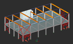
1736865314584.png

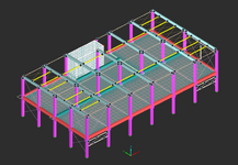
2) I did linear buckling analysis just of the front wall in Robot (I assuming that it must take the horizontal force from half of the columns - another half will be taken by a stairace). I've created structural model, bottom bracing as a hollow sections, and top bracing by pre-tensioned (tension only) elements:
1736865415525.png
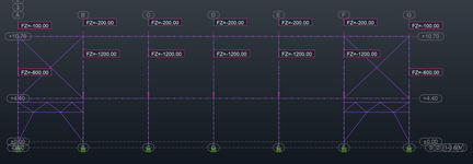
3) I put some loads [kN] which are lower that in 3D model, but they're proportional to each other (those in the slab level to those on the top):
1736865615433.png
4) Results of LBA - first buckling shape for columns:
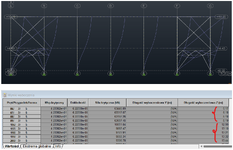
1736865767512.png
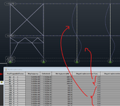
How should I read the results? - isn't it weird that shape is not more like S? I suppose that the stiffness of the bottom bracing is too low compared to stiffness of the columns themselves? - but to be honest I think it's a REALLY big bracing. The is nothing about a stiffness of the bracing in Eurocodes. I've found the condition from AISC Appendix 6, but the required stiffness of bracing is not dependent on the stiffness of the columns..

From what I get, bottom part of columns has about k=1 (element numer <196), and the top part k=2 (element number >=196). Is that correct? - someone told me, that I cannot read two different k's from one drawing, cause it's the same continous curve and I'm stuck with it.. Could anyone help me understand what I'm doing wrong?

Disclaimer: when I've created a model with steel columns/beams (rectangular hollow section 200x5 mm), then it looks better - but even in this kind of model, am I doing it right or missing something important?
1736867105811.png
 

Attachments

  • 1736865740647.png
    1736865740647.png
    99.2 KB · Views: 6
Last edited:
Replies continue below

Recommended for you

I think your problem may be that you aren't utilizing the floor and roof beams to act as a moment frame. I am assuming that those beams are also concrete.

It is not common to use steel braced frames in the same location as a concrete moment frame.
 
As I wrote, the connections are not stiff, precast beams are just laying on the column corbels (of course there will be 2#20 rebars to connect it) - I treat it as a pinned connection and in Robot concrete beams are pinned on both ends.
 
Are your shear walls strong enough to resist all lateral loads?

Is the diaphragm stiff?

If yes to both, wouldn't the diaphragm be bracing the column?
 
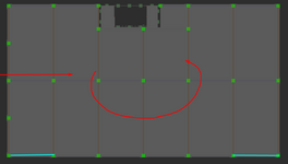
Shear walls (from staircase) are very eccentrically positioned and I'm affraid of torsional moment:
1736874304970.png

I think that diaphragm from concrete hollow core slabs is stiff (there is concrete between slabs, and it will be also connected to precast concrete beams by a cast-in-place ring beam) but I wanted to use it only to distribute loads between bracings.
 
You're right.

I was searching for information about force that my bracing need to bear in case of concrete columns - there was a thread about something like that here on this forum. There was no real conclusions if it's different from steel columns - opinions were divided between 2% (as for steel columns) and 5% (from some local codes and it was about shoring columns).

I'm trying to understand what I'm doing wrong with LBA and if there is an influence of the stiffness of column to required stiffness of bracing (even if it's not in the Appendix 6).
 
I’d be using the columns to stabilise it. It’s a short building.
 
I’d be using the columns to stabilise it. It’s a short building.
I think part of the issue is that the concrete is pre-cast. Getting connections to work rigidly between seperate pre-cast elements is annoying, and would take quite the coordination between the supplier and the EOR. OP Could always prescribe a design moment/shear and have the supplier design the connections for this.

But at that point, I'm not sure why concrete columns/beams are being used at all. Seems like this would be better suited with hollowcore sitting on steel beams tying back to steel columns, which makes integration of your steel cross braces much easier.

Also, OP you appear to have your cross braces modeled such that they do not interact with eachother at the crossing point. If this is your intent, you need to make sure the supplier doesn't add a hinge here to tie it all together. You might be better off having one member be drawn from corner to corner, and the other be drawn from corner, to midpoint of X-brace, down to the bottom corner.
 
I think part of the issue is that the concrete is pre-cast.

Yes, that’s doesn’t help, however there appears to be space for top floor bracing which stabilises the columns.
 
but to be honest I think it's a REALLY big bracing. The is nothing about a stiffness of the bracing in Eurocodes.
Your thought implies you are at Eurozone . Is that true?
You can reinforce the concrete with steel having Es almost 10Ec. In your case , the cantilever column system fixed at foundation level ( probably with using pocket found.) still could be more stiff than a tension only bracing located at a few place.

My approach would be ;
- Design the columns two storey cantilevers considering the second-order theory, and ensure that diaphragm requirements satisfied with topping conc.

- In case of seismic zone , i would consider adding shear walls keeping symmetry ( Precast or cast in place ) or PC moment frames.

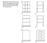
The following excerpt from Betonkalender Precast Concrete Structures
1736928573752.png
Your
 
Last edited:
I think part of the issue is that the concrete is pre-cast. Getting connections to work rigidly between seperate pre-cast elements is annoying, and would take quite the coordination between the supplier and the EOR. OP Could always prescribe a design moment/shear and have the supplier design the connections for this.

But at that point, I'm not sure why concrete columns/beams are being used at all. Seems like this would be better suited with hollowcore sitting on steel beams tying back to steel columns, which makes integration of your steel cross braces much easier.

Also, OP you appear to have your cross braces modeled such that they do not interact with eachother at the crossing point. If this is your intent, you need to make sure the supplier doesn't add a hinge here to tie it all together. You might be better off having one member be drawn from corner to corner, and the other be drawn from corner, to midpoint of X-brace, down to the bottom corner.
Concrete columns are the choice for this type of buliding because of the fire design (R60) - noone wants to paint steel column - general contractor I'm working with uses concrete columns in 90% of bulidings.

Sorry, but I don't get what you've meant (could you sketch it?) - I consider X bracing as #24 mm steel round rods, they will not connect to each other. I will be making a detail drawings, so I have a total control over every aspect - I will also have an "author's supervision" over the whole object.

BTW: what does OP mean?
 
Yes, that’s doesn’t help, however there appears to be space for top floor bracing which stabilises the columns.
I ended up with something link this (see attachement). I was also thinking about making a stiff X brace from the slabs to the top of the columns, but I've decided that the bottom truss will be better.

My only concern now is - how to check these bracing to be sure, that bottom part of my columns will have a k=1.0 (in both directions), and the upper part on the perimeter k=1.0 (in a plane of bracing) but upper parts inside the building (in both directions) and upper parts of columns in perimeter (out of plane of bracing) I will consider as k=2.5 (bottom support is not stiff as much).
 

Attachments

  • Screenshot 2025-01-17 011032.png
    Screenshot 2025-01-17 011032.png
    275.3 KB · Views: 5
Your thought implies you are at Eurozone . Is that true?
You can reinforce the concrete with steel having Es almost 10Ec. In your case , the cantilever column system fixed at foundation level ( probably with using pocket found.) still could be more stiff than a tension only bracing located at a few place.

My approach would be ;
- Design the columns two storey cantilevers considering the second-order theory, and ensure that diaphragm requirements satisfied with topping conc.

- In case of seismic zone , i would consider adding shear walls keeping symmetry ( Precast or cast in place ) or PC moment frames.

The following excerpt from Betonkalender Precast Concrete Structures
View attachment 3517
Your
Yes, you're right.

I tried to design it as continous 2 storey column, but then buckling length would be 2.18*11.3 m = 24.6 m which is too much - 50x50 cm is not enough in this case, and I cannot design bigger section at this time.

Could you elaborate your approach? - how would you consider 2nd-order theory? (added equivalent horizontal forces like it is in a steel structures?) - in eurocodes there are two design approaches - nominal stiffness and nominal curvative and these consider 2nd-order theory but the global calculations are made in 1st order as I understand it right.

"and ensure that diaphragm requirements satisfied with topping conc." - I'm sorry, but I don't get this part.

No, fortunately there is no seismic zone here ;)
 
You should use 60x60cm columns (to keep slenderness at about 140) and forget about any bracings (as @HTURKAK said - use cantilever columns system with pockets).
Also my recomendation is to separate staircase walls for lateral loadings. therefore you will not have eccentricity problems.

Anything else will probably get your contractor to "roll eyes" and find another engineer eventually.
 
Could you elaborate your approach? - how would you consider 2nd-order theory? (added equivalent horizontal forces like it is in a steel structures?) - in eurocodes there are two design approaches - nominal stiffness and nominal curvative and these consider 2nd-order theory but the global calculations are made in 1st order as I understand it right.
The following clauses from EN-1991 5.8 Analysis of second order effects with axial load
-First order effects: action effects calculated without consideration of the effect of structural deformations, but including geometric imperfections,
-Second order effects: additional action effects caused by structural deformations ( P- Delta effects..)

- Floors shall be designed as horizontal diaphragms.( with reinf. overtopping screed etc)
 

Part and Inventory Search

Sponsor