Continue to Site

Eng-Tips is the largest engineering community on the Internet

Intelligent Work Forums for Engineering Professionals

  • Congratulations SSS148 on being selected by the Eng-Tips community for having the most helpful posts in the forums last week. Way to Go!

Bracings configuration in steel frames

Status
Not open for further replies.

SKJ25POL

Structural
Mar 4, 2011
358
I have few questions on bracings in steel frames:

1- Shall the bracing configuration stays the same in all floors/levels of the bay that is gonna be braced? I mean does it need all floors be like x-braced?

2- Can we use tension/tension bracing (such as x-bracing) in one story and tension/compression bracing in the below story? Does this mess the load pass or not?

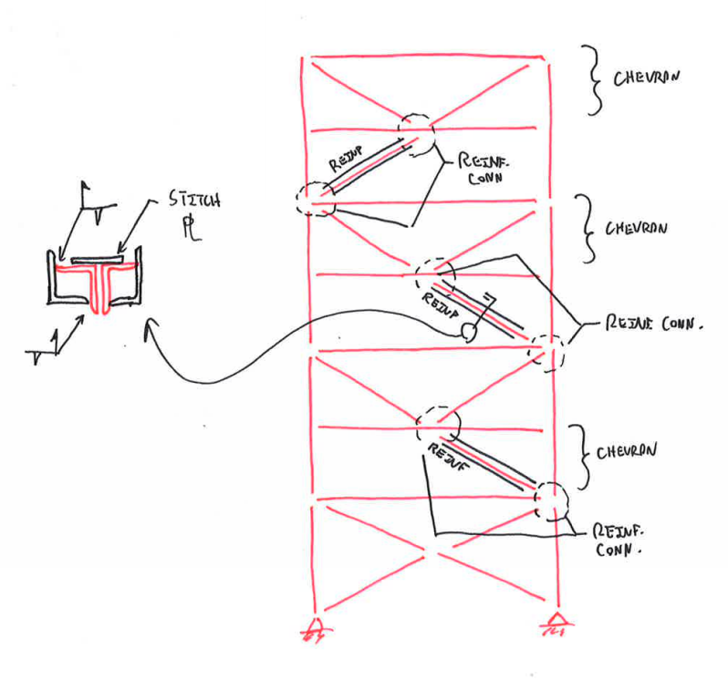
3- if we have a one bay bracing situation and for some reasons(cutting an opening in the wall) one half of bracing in one direction get cut(please see the attachment) is the other reaming half work or can be of use?
What is the best solution for the attached situation.
How I can compensate the cut bracings?

I appreciate for kind advise.
P.S. Please don't make a comment of "ask more senior engineer in your office" - if I had that choice I would and not bothering you. Thanks
 
 http://files.engineering.com/getfile.aspx?folder=b1c676cb-4e29-439f-9730-1a53c0f0b207&file=Bracing_cut.pdf
Replies continue below

Recommended for you

You can indeed do everything that you've proposed. Essentially, your upper three levels will all become singly braced (T&C) braces as you've rightly identified. Some consequences:

1) Depending on your jurisdiction, this may create a vertical stiffness irregularity for seismic loads. That doesn't necessarily mean that you can't do it; you just have to absorb some penalties.

2) Based on the sizes of the original braces, I agree that they were probably designed to be tension only. To make them work as tension/compression braces would probably require serious reinforcement. You may be further ahead to just get rid of them and replace them with tube / wide flange sections.

3) The original brace connections may not have been designed to handle compression loading. That could require some attention.

One nice thing about the tension only bracing is that it likely means that your members are already designed to handle the loads associated with a single brace per bay scheme.

I like to debate structural engineering theory -- a lot. If I challenge you on something, know that I'm doing so because I respect your opinion enough to either change it or adopt it.
 
In some codes, in higher seismic areas, you aren't allowed to have all tension braces or all compression braces but have to balance them out along any one line of bracing in each story.


Check out Eng-Tips Forum's Policies here:
faq731-376
 
I would be inclined to add a line of columns where the current bracing crosses each other the whole way up. Then provide new cross braces in the bays without openings.

Or something along those lines. you could even turn them into K braces (or chevron, I never remember which is the right terminology) but that still requires them to be T/C braces and it's likely the existing members can't take the C if they're only designed for T.
 
Thank you KootK (Structural) and Thank you jayrod12 (Structural).

jayrod12 (Structural),
I was exactky thinking to use what you proposed except that I was not thinking to run a middle column all the way.
I knew that something doesnt feel rigth but didnt occure to me to run a column and tie the not opening side with another diagonal same direction as the one cut.

Thank you that was such relief for me to know that option requires running a middle column. But the bad point is that it is extra cost to run a column for three/four stories and connecting it to existing foundation.
 
Can't please everyone. The cheapest way to do it would be to not cut the bracing and move the door openings to accomodate the bracing.

But that's never an option either.
 
The intermediate beams make me curious. Might they be physically attached to the cross braces so that they are providing out of plane bracing to them? If so, you might have some more economical alternatives.

I like to debate structural engineering theory -- a lot. If I challenge you on something, know that I'm doing so because I respect your opinion enough to either change it or adopt it.
 
KootK (Structural,
Yes the bracings are connected to the intermediate beams.
What are the more economical solutions to compensate the cut of one leg of x?
Could you please draw a sketch of your toughts. I greatly appreciate it.
Pics and sketchs communicate better.

Thank you very much
 
The presence of the intermediate beams connected to the bracing leads me to speculate that the original bracing may have actually been tension/compression bracing instead of tension only bracing. If that's the case, then the upper half of each bay should constitute a chevron brace that will remain unchanged by your alterations. You would simply need to reinforce the struts in the lower half of each bay as shown below. And, perhaps, the connections involving those struts.

Capture_m1m0yj.png


I like to debate structural engineering theory -- a lot. If I challenge you on something, know that I'm doing so because I respect your opinion enough to either change it or adopt it.
 
I need to modify my previous suggestion. The upper chevrons will be affected by the additional upward thrusts of the single braces below. Do some modelling to confirm but, in essence, I think that the remaining half of the cut brace will essentially become ineffective. You'll be left with a single tension/compression brace in each bay. However, the intermediate beams are still good news. It cuts down the length of the braces in compression by half and should make the reinforcing quite modest.

I like to debate structural engineering theory -- a lot. If I challenge you on something, know that I'm doing so because I respect your opinion enough to either change it or adopt it.
 
KootK (Structural,

Thank you so much for your sketch and the idea.
Idont completely understand, "The upper chevrons will be affected by the additional upward thrusts of the single braces below." Could you possibly call the members and say it is structural anlaysis way what force (of what member) will affect which one?

Thank you so much

And also one other question flashed in my mind, it is okay that we have the three upper stories tension/compression and the very bottom floor have a X - bracing (or tension/tension bracing)?
This gets back to my initial posted question that can we have one type of bracing in one floor and different type in below floor?

Last question (that is a general question on bracings) with tension/compression bracing does it mater what direction we lay the diagonal?


Thank you and have good long weekend.
 
You're most welcome SKJ25POL. I'd recommend just firing up the computer and figuring out what your forces are and which members require reinforcing. It is ok to have different bracing schemes at different levels. And, JAE's comment excepted, it usually immaterial which direction you run your braces.

I like to debate structural engineering theory -- a lot. If I challenge you on something, know that I'm doing so because I respect your opinion enough to either change it or adopt it.
 
If you look into what KootK is suggesting, pay attention to the beam under each modified bay as well. It's now a tie beam that's transferring force back to the other side of the bracing system for the next floor down. If it was designed as a tension brace system originally, this was already accounted for. If it was tension-compression of some sort, they may have assumed that they were passing most of this load directly between braces. This is likely not going to change much, but it could have some connection implications and if you have high brace forces or the beams were designed close to capacity you may have a strength issue in the beam.
 
Status
Not open for further replies.

Part and Inventory Search

Sponsor