Continue to Site

Eng-Tips is the largest engineering community on the Internet

Intelligent Work Forums for Engineering Professionals

  • Congratulations KootK on being selected by the Eng-Tips community for having the most helpful posts in the forums last week. Way to Go!

Brain warm-up requested. 2

Status
Not open for further replies.

itsmoked

Electrical
Feb 18, 2005
19,114
Hi! I have a customer with a mid-size machine shop with lots of different types of machine tools. About 2 years ago I was introduced to the place because a large CNC tool sporadically threw error codes occasionally when a tool-changer was operated. Turned out that a control transformer was tapped at a percentage point that on hot days (low PG&E voltage) was below a functional output. I up-tapped 3(!) taps to get the voltage centered on requirements and all has been well.

Until recently...

That same unit had it's $4k spindle drive motor toast.

Now there's a lathe that throws bizarre error codes out of a controller that stops the machine in its tracks. The guy finds another sub-unit on ebay, buys and installs it. It throws the same exact code! He calls the seller and the seller tells him the only time he ever sees that strange code is when the units are installed into an OPEN-WYE OPEN-DELTA (please read what I mean not what I type) system that has issues. He went on to say he saw it at a place where it threw codes only on weekends because the neighboring business were not running. He suggested turning on every induction motor he has to see what happens. Doing this made a difference!

The customer also stated that a machine with a 7-1/2hp motor is fed by a conduit that runs thru his office. In the last year he's realized he can hear that conduit buzzing a little when the motor is running and it has slowly gotten louder and louder.

Most machines have buck transformers to get the ODelta 240Vac down to 208V (Japanese machinery).

Yesterday PG&E showed up and installed a power monitor ahead of his meter and have since told him, "There's something strange happening.".

We're awaiting their written report (later today??).

Any suggestions popping into your heads?
Antidotes?
Things to check?
Changes to make?
Watch-outs?


Keith Cress
kcress -
 
Replies continue below

Recommended for you

Sounds very weird. My first thought would be to check voltage & resistance on the lines to that 7.5hp motor. Maybe a loose connection or failing wire insulation in the conduit? Might be enough to drag a leg down or shunt enough current to earth to cause issues.

That being said, I am NOT known for troubleshooting power problems...
 
Possibly a failing buck transformer.
That conduit noise may be a ground current being conducted by the conduit.
I am familiar with the open wye connection but I have never seen one in the wild.
It is possible to derive 120/208 Volts three phase from two phases and a neutral.
The one engineer who I found that was familiar with the connection called it a "Winnipeg" connection.
A primary winding in a buck transformer failing to ground could cause strange things to happen.
How are your buck transformers configured?

Bill
--------------------
"Why not the best?"
Jimmy Carter
 
Correction... Open Delta not "Winnipeg".
I'm grappling with one of my biggest customer's facility having half burnt down yesterday.. [sadeyes]

Keith Cress
kcress -
 
I wish I could help.
Pictures? grin, not really.

Bill
--------------------
"Why not the best?"
Jimmy Carter
 
Power electronics and delta power systems, not good. Power electronics and OPEN delta, even worse! The problem with delta services is the inconsistent voltage reference to ground, usually floating and in the case of open delta, almost ALWAYS floating (except in SWER systems). Inside of your CNC machine, the servo amps and any VFDs will likely have Common Mode Noise filters and MOV systems that are all referenced to ground, but the ground is not referenced to the line.

The best solution is to install a 1:1 "drive isolation transformer" that will give you a 240/138V solidly grounded wye on the output, it provides for a consistent ground reference for all 3 phases (you wouldn't use the 138V). This is basically what is happening with the 208V equipment already; it's a 208Y with a solidly grounded neutral.


" We are all here on earth to help others; what on earth the others are here for I don't know." -- W. H. Auden
 
I must disagree with jraef. All the open deltas I know of have one winding center tapped and grounded, providing a ground reference. It's not a balanced reference, since one leg is high.

Open deltas can have unbalanced voltage without the third winding to balance things.

What winding configuration dd the 240-208 transformers have?

Get that report yet?
 
stevenal said:
I must disagree with jraef. All the open deltas I know of have one winding center tapped and grounded, providing a ground reference. It's not a balanced reference, since one leg is high.
I agree with Steve.
Open delta phase to ground voltages and phase to neutral voltages are 120v, 120V and 208V to on the wild leg.
The wild phase is generally more of an issue than possible unbalances.
Uneven loading of distribution phases is the cause of most unbalances.
Current on the distribution circuit neutral and the resulting voltage drop are the main cause of unbalances.
Voltage regulators correct the line to neutral voltages, but in the case of significant neutral current may increase the line to line unbalances and the phase angle errors.

Open deltas and primary unbalances.
Often an open delta is formed when a relatively small teaser transformer is added to a larger 120/240 Volt single phase transformer to supply a relatively small amount of three phase power.
The open delta is an unbalanced load on the primary, but how important is it?
The neutral voltage drop that is the cause of the issues is a simple IR drop and increases with distance.
In a built up area the neutral current will be balanced out in a relatively short distance by other single phase loads on the primary circuit.
Open deltas often perform well in built up areas.
Exception #1. Long rural lines.
The greater the distance from the open delta bank to other loads that may cancel out the neutral current, the more problematic unbalances may become.
But, three phase wye transformers may suffer some issues also. These issues generally won't affect the transformer but will be a problem with motors.
Exception #2 large loads on long rural lines.
In the case of a large load far out on a rural line it may be cost prohibitive to run three phase conductors.
In this case, the open delta may consist of two larger and equally sized transformers.
This will cause a greater voltage drop on the neutral and greater unbalances. The issues for connected motors are both unbalanced voltages and phase angle errors.
That said, such long rural circuits are often further degraded by voltage regulators.
Mitigation.
1.- Oversized motors.
2. A wye/delta isolation transformer with a floating primary wye point. If a ground reference is required it may be developed by a second, smaller wye delta transformer bank. Often small lighting transformers may be used. The wye point of this bank is grounded and forms both the neutral and the grounding point.
So we have an open delta bank rated to carry the full load, a wye/delta isolation bank rated to carry the full load and a wye/delta bank that will support enough current to trip the circuit breaker in a short time.
Is that costly?
The relative cost to avoid several miles of adding a third phase conductor may outweigh the cost of mitigation.
On a long rural circuit a three phase wye/wye transformer may also have unbalance problems that may have to be mitigated for the motors.
A three phase transformer with a three legged core is not a good idea on long three phase circuits due to the heating caused by the phantom delta.

Keith, the topography of the supply circuit may play a part in trouble shooting these issues.
The cause may be internal, but it may be the result of an added load or a removed load on the primary circuit.
I have seen serious issues from both causes.


Bill
--------------------
"Why not the best?"
Jimmy Carter
 
stevenal; No report divulged by the customer to me yet, though admittedly, I'm swamped at the moment and hence not chasing it. I'll call today to see.


Bill; Not rural at all. Across the street from a Best Buy, Safeway, and Home Despot.
Surrounded by restaurants, furniture stores, and sharing a building with about 4 other companies. I haven't been there in about three years, since the earlier fix, so I'm not sure if there's one bank serving the whole building (probably) or a separate one for them. I just know it's 240 Open Delta and he's used (I believe) scads of open delta buck transformers on each machine to get the 240 down to 208 for everything since it's all Asian stuff wanting about 200V.

Keith Cress
kcress -
 
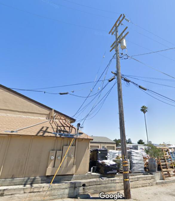
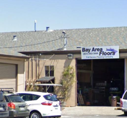
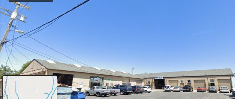
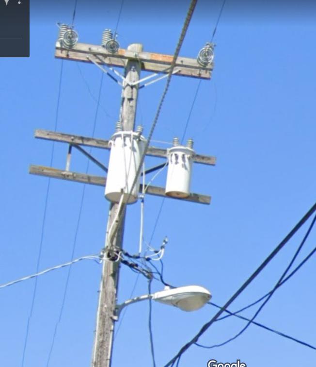
Lookie what I found on Goggle.

Everything on the pair of transformers.

This morass (heavy on ass):

Front_half_gf0gh2.jpg


Plus this where the shop drop is:

Back_supply_bozt9x.jpg


Shop is on the far right and is a crammed machine shop:

whole_shmo_jxgwds.jpg


Here's the pole pigs.

Pole_pigs_ybg5bn.jpg


Keith Cress
kcress -
 
Hi Keith.
That looks like the feed to a machine shop that I used to service.
Fortunately it was all DOL motors and the system had no issues.
When I see that arrangement, it is often a typical single phase circuit with the larger transformer feeding a number of customers.
I think that I see 7 revenue meters, not sure.
It looks like three service drops from that bank. 7 meters plus?
There are two possible primary issues as well as the issue that you previously addressed of low voltage on hot days.
1. Primary voltages and issues.
a) On hot days the load induced voltage drop on the primary phases may not be equal.
The load demographic of "comfortable" customers with lot of A/C is very different than the load flow demographic of financially challenged customers with little or no A/C.
As a result the load balance of the primary circuit may be varying with the time of day and the ambient temp. (A/C use)
I can bring anecdotes.
b) The primary neutral may be compromised.
The primary neutral current may be returning on the grounding path with higher than normal neutral voltage drops.
2. Secondary voltages and issues.
Problems originating on the secondary side may be unequal loading.
The large transformer regulation will depend on the loading of the large transformer.
Add to this that PG&E may be allowing the larger transformer to be overloaded on hot days.
With this type of open delta application the teaser transformer is often lightly loaded with good regulation.
Summary:
Possible issues;
Unequal primary loading and voltages.
Compromised primary neutral.
Unequal secondary loading and regulation.

Now draw the vector diagram for an open delta with unequal phase voltages and use a dotted line for the open phase.
You will not have an equilateral triangle.
Phase angles will be unequal also.
A compromised neutral, from a neutral voltage drop, possibly made worse by a high resistance neutral return path will make the situation worse.

If that 7.5 HP motor is line connected it will not be happy.

I have an idea.
I am open to comments from others here.
If all else fails I would consider installing a wye/delta bank to feed the problem machines(s).
Leave the wye neutral floating.
A 120:240/120:240 Volt transformer(s) will give you the 240 Volt delta that Jeff mentioned.
Three small auto-transformers in grounded wye will give you a symmetrical ground reference and neutral at near 120/208 Volts.

An induction motor is also acting as an induction generator.
The difference between the applied voltage and the back EMF generated by the induction generator action is what drives the motor and limits the current.
The induction generator output is fairly well balanced.
Consider the induction generator as three single phase generators in parallel with three single phase lines..
When the parallel voltages are unequal, fairly heavy reactive current flows.
When the phase angles are off, the leading phase(s) will transfer power to the lagging phase(s)
This causes heavy real current as energy is transferred from the leading phase(s) to the lagging phase(s)
These currents are limited by the source impedance and the motor impedance.
OP said:
He suggested turning on every induction motor he has to see what happens. Doing this made a difference!
Yes, it would and points to an unbalance problem.
The more motors are on line the less the collective motor impedance.
The currents, both real and reactive follow Newtons law. For every action there is an equal and opposite reaction.
The currents act to correct the factors causing them.
If you measured the voltages and phase angles of the transformer, you would see that the voltage balance improves when the motor is connected and is trying to correct the unbalances.
As more motors are connected, the transformer balance is improved and the voltage balance at each motor will improve.
Tip; The line impedance from the transformers to the motors is relatively low enough that measuring the voltage anywhere between the transformers and the motors will show the improvement as more motors are started.
No need to try to measure at the transformer terminals.
Comes under the dual headings of:
1> I never wanted to be the smartest electrician. I always wanted to be the oldest electrician.
2> Being a smart electrician goes a long way to becoming the oldest electrician.
When you are working in the field as an electrician, Work smart and work safe, my friend.

Bill
--------------------
"Why not the best?"
Jimmy Carter
 
stevenal; I called today but the guy had left early and thru the grape-vine I heard that PG&E still hasn't reported yet.

I also heard that they've put a big motor from a phase converter online (though why would it be 3ph??) and it's helped the balance considerably.

OK, so if PG&E is as lame as I expect them to be and they can do nothing -possibly because all the other 7 business are misloading the phases- what's the all-in solution? A BIG transformer as Jeff suggests or a big...25hp idling induction motor? A motor seems pretty lossy not to mention the heinous lagging pf it would inflict. However I doubt this location has a pf charge though they could.

Every machine has two buck transformers. Perhaps a third one hooking each up with a floating neutral wye?

Keith Cress
kcress -
 
Hi Keith.
Are these line connected motors or VFDriven?
Have you checked your line to line voltages?
Setting the teaser transformer tap down a step or two may help.
The teaser will probably be lightly loaded while the main transformer is heavily loaded.
The motors, as induction generators try to correct this by attempting to pull down the voltage of the teaser and pull up the voltage of the main transformer.
Setting the teaser voltage lower will bring the voltage match closer, but at light loads you will have the opposite effect when the main transformer voltage goes above the teaser transformer voltage.
It's a compromise that will not completely cure the issue but may give a large measure of relief.
As i have said, the motor is trying to correct the voltage problem. As more motors are added, they share the burden of correction.
The lower combined motor impedance causes more circulating current through the transformer, and an improvement in voltage balance.
The real solution is a three transformer bank.
Probably 120/208 Volts wye. That gives you a better voltage to your Japanese motors.
A compromise is a three phase transformer matched to the actual load. A why/delta with a floating wye point will still develop unbalanced voltages on the secondary but the smaller size makes it easier for the motors to correct the voltages.
Actually they hit a happy medium with part of the IR losses of the circulating current lost in the transformer and part lost in the motors.

Bill
--------------------
"Why not the best?"
Jimmy Carter
 
By the way, It's not a good idea to add a third transformer to an open delta with a teaser transformer.
Due to the way that a delta bank shares a single phase load, an undersized transformer may become overloaded and burn out due to a heavy single phase load on another phase.

Bill
--------------------
"Why not the best?"
Jimmy Carter
 
I also heard that they've put a big motor from a phase converter online (though why would it be 3ph??) and it's helped the balance considerably.
It is probably a three phase motor with the third phase developed partly by capacitors and partly by the action of the induction generator.
In this case it is probably connected as a three phase motor.
And more motors sharing means...

Bill
--------------------
"Why not the best?"
Jimmy Carter
 
Howdy Bill,
Are these line connected motors or VFDriven?
These are all VFD or servo drive do-hickys.
Have you checked your line to line voltages?
Have not been there this episode.
Setting the teaser transformer tap down a step or two may help.
You mean the bucks?
The motors, as induction generators try to correct this by attempting to pull down the voltage of the teaser and pull up the voltage of the main transformer.
Ah, I get it now. OK makes sense.
Setting the teaser voltage lower will bring the voltage match closer, but at light loads you will have the opposite effect when the main transformer voltage goes above the teaser transformer voltage.
It's a compromise that will not completely cure the issue but may give a large measure of relief.
I can see that. What a PITA since you've got 7 other businesses running off that same set of transformers. I can see chasing that all over.
The real solution is a three transformer bank.
Probably 120/208 Volts wye. That gives you a better voltage to your Japanese motors.
I can totally see the neighbors nixing that. "We don't have any problems and don't want to cause any changing anything." Dang.
Due to the way that a delta bank shares a single phase load, an undersized transformer may become overloaded and burn out due to a heavy single phase load on another phase.
That's what I was afraid of.
In this case it is probably connected as a three phase motor.
Yes, You're probably right on about that. Yep, they are actually 3ph motors.. I'd forgotten that.

What if we go with Jeff's 1:1 and we use a single LARGE transformer for all his machines. Doesn't this still cause him to be billed for any circulating currents - (transformer heating)? If so I could see a big bill for no real work and the imbalance could be really big on sat and sun with way more circulating current.

He needs a 200A motor-generator set. LOL

Or, one of those units that are a single frequency inverter that takes in whatever and synthesizes the 3ph out. Phase Perfect

Keith Cress
kcress -
 
Hi Keith.
I started to answer a few days ago but my failing computer re-booted and I was out of time. (New computer coming for Christmas)
Then life got in the way. On the hockey bus the next day. Will had an away game. They won. Presently #1 in their tier (Bantam tier 2), but the season's young.
I digress.
Back to your issue.
First, we are missing quite a bit of hard data.
Rather than authoritative answers please consider this as a discussion based on first principles and assumptions between knowledgeable friends.
Assumption #1.
The other customers are single phase. That arrangement of a large transformer and a much smaller teaser transformer is typically used when only one of several customers needs a small amount of three phase power.
Assumption #2.
As this is in a built-up area the grid and particularly the neutral should be reasonably stable.
We will discount for now effects tat may be caused be a primary neutral shift.
Assumption #3.
The large transformer is heavily loaded. The teaser transformer is lightly loaded.

Questions and suggestions.
Drives with rectified front ends.
As i understand drives and three phase rectifiers, unbalanced voltages and phase angle errors cause the rectifiers in one or two phases to work a little harder.
If a drive is throwing error codes I would first suspect the offset ground/neutral inherent in a four wire delta to be the cause.
If the teaser voltage is running high as I suspect, adding more drives will load the teaser and the voltage will drop, showing some improvement.
Three phase motor(s) will act to correct the phase angles as well as the voltages.

By the way, is the 7 1/2 HP motor on-line or is it drive controlled.
Are there any three phase motors on-line without drives?

Reality check;
I have used a similar method to do a power factor survey of a large number of motors.
Measure the line to line voltages.
Draw them out to scale on a large sheet of paper. (Remember your high school geometry and constructing triangles).
This will show both unbalanced voltages and phase angles.
A good angle at the common connection between the main transformer and the teaser transformer goes a long way to ruling out primary issues.
This is valuable data but we still don't know if the root problem is unbalanced voltages and angles or the asymmetrical ground reference.
Generating a symmetrical reference point:
DON'T call this a neutral or a ground. Doing so will invoke some NEC rules that are not applicable.
This is a symmetrical reference.
Simple. Connect three of your little buck-boosters in star delta.
The delta just has to be on the same voltage and taps. It is not used directly.
The wye point will form a symmetrical reference point.
DON'T GROUND THE SYMMETRICAL REFERENCE POINT NOR CONNECT IT TO THE SYSTEM NEUTRAL.
If the source of the error codes is an unsymmetrical neutral this should address the issue.

Unequal voltages.
Compare the main transformer voltage with the teaser transformer voltage.
Use a buck-boost to match the voltages.
Feed the primary from the phase on the teaser transformer, not from the open delta.
Driving the primary of the buck-boost with a Variac will give you a lot of leeway when trouble shooting.

The PG&E report.
A three phase motor has a lot in common with a wye/delta connection in regards to power transfer.
Both arrangements have the ability to transfer power between phases.
The power transfer may be 10s of kW or 100s of kW, or more, depending on the topology of the system.
A phase to phase connected Power-meter may show results that do not reflect the known connected load.
If the Power-meter is connected with the asymmetrical neutral as the common point, rather than line to line metering, the results may get stranger.
Trim for minimum current on the outgoing line.
As I said, a lot of assumptions. Feel free to correct and discuss.

Bill
--------------------
"Why not the best?"
Jimmy Carter
ps Season's Greetings
 
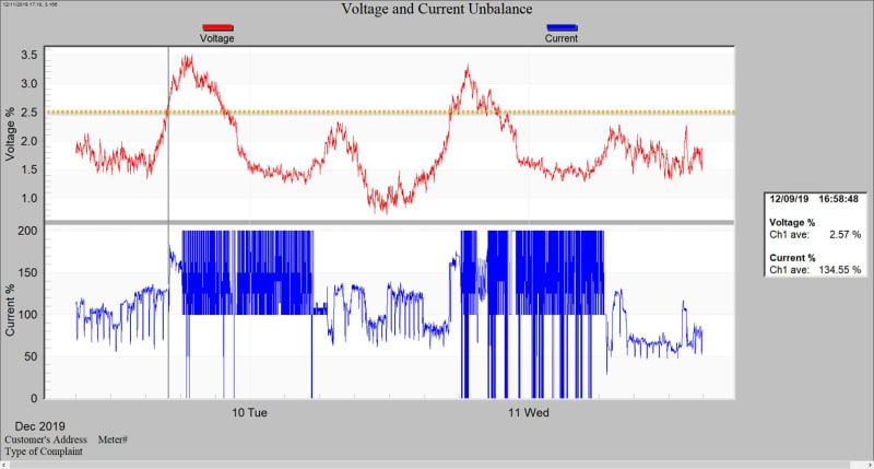
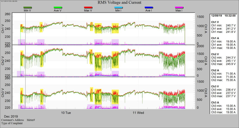
So PG&E came back with a power report finally. They connected their instrument between the pole and the weather head.

image001_s77tvg.jpg


image002_dfdqeq.jpg


image003_wcijbo.jpg


Their "Rule 2" requires they keep the voltages between +/-5% nominal (228~252V). As can be seen it's rising above +5% everyday right at end of business and staying that way thru midnight when I'm guessing some pole mounted voltage regulator does its thing on the primary voltage.

BTW: These problems all started last fall when an underground vault transformer exploded about two businesses away. When power came back at this business a $4k drive was dead and machine misbehavior has now been the norm.

PG&E's solution is to "re-tranformer" the pole with "two new transformers to correct the voltage". This will take place in approximately 6 weeks.

Note the Ch2 current difference. Can you explain this?

I'll be visiting the site tomorrow (Fri) for the first time.


Keith Cress
kcress -
 
I'm guessing that the motor is drawing more current from the higher voltage phase.
ch2 ave: 245.1 V, 71 A
And through induction generator action supplying part of the current drawn by the lower voltage phases.
ch1 ave: 241.2 V, 19 A
ch3 ave: 237 V, 15 A
It appears that the motor may be supplying the greatest portion of the load on the phase with the lowest voltage. That is, the greatest reduction of current.

From the Voltage and Current Unbalance chart:
Again guessing.
It looks as if there is a very large single phase load (oven?) cycling on a thermostat.
I don't understand the sharp cutoff at about 100% unbalance at the bottom of the area where the pen is "Painting the chart".
There doesn't seem to be any correlation between the current unbalance swings and the voltage.

The best case for an open delta is where the two transformers have the same regulation and have about the same percentage loading, hence, about equal voltage regulation under load.

By the way, from your photo of the transformer bank, it appears as if the center tap of the larger transformer has a cable connected.
Some of the customers may be single phase only.
That also means that you probably already have a ground reference.
The phases will be 120 Volts, 120 Volts and 208 Volts to ground.


Bill
--------------------
"Why not the best?"
Jimmy Carter
 
Hi Bill! No heaters, all big machine tools. I can see the spikes as being cuts and the non-spikes being simply translations or tool changes etc.
Almost all the other 7(?) businesses are indeed single phase only, using lights and such.

Yes, good point about there already being a ground reference.
It's not clear to me if channel 2 is the stinger or not.

I think you're on to something with the higher voltage phase supplying all the amps. This would make a whole lot of sense because all the loads but about two are rectifier front-ends. The rectifier confronted with the highest voltage is going to hog all the current needed to charge the cap banks.

Talking to the owner today all his machining centers each have a "buck" transformer (he calls them). He described classic vertical E core configurations with coils on "each arm of the E". I'll lay eyes on them tomorrow.

Also, PG&E stated that three transformers delivering 208V would be best (as you stated) but they said it would cost a fortune as they would have to put in another pole and set of transformers and he's have to pay for it all.


Keith Cress
kcress -
 
Status
Not open for further replies.

Part and Inventory Search

Sponsor