Continue to Site

Eng-Tips is the largest engineering community on the Internet

Intelligent Work Forums for Engineering Professionals

  • Congratulations KootK on being selected by the Eng-Tips community for having the most helpful posts in the forums last week. Way to Go!

Breakout of I-Beam Cast in Concrete 1

EngDM

Structural
Aug 10, 2021
452
Has anyone here ever analyzed a steel I-Beam cast in concrete for breakout? Some ideas I have are to add nelson studs to the web of the beam, or add weldable rebar to the sides/bottom, but I have never actually seen any calcs or procedures for this. I've got some pretty high tensile loads to resolve. Just wondering if there are some "typical" details or simple details that have been developped that I could look into.

Top of concrete is top of top flange, equipment is then welded to the top flange.
 
Replies continue below

Recommended for you

The OP should give more info for the loading and provide a sketch . If it is pure moment , ( no lateral load with lever arm..) and the couple is applied to the top flange at extreme points , imo , the use of welded shear studs could be considered to improve the strength .
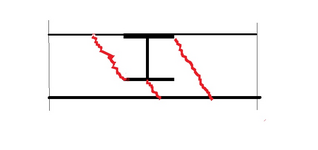
With limited info . provided , breakout should be shear failure at opposite sides rather than pull out. I have provided a simple sketch for breakout scenario.

My vote would be the use of thick anchor plate rather than embedded WF.
1733471950161.png
 
How concerned are you about maintaining SOG reinforcing continuity across this thing? I would not relish the idea of the beam becoming a big contraction joint.

How long will one of these beams be?
Rebar doesn't need to be continuous. Given that the slab is probably going to be 12" thick under the beam already to satisfy flexural requirements of the slab itself, I could always hook the bars down and develop underneath. The beam is 12'3" long and located nowhere near the true edge of slab. The approach I am taking is to provide thicker slab areas under these beams and step back to a regular 6" SOG once I've developped my capacity and bearing area.

I agree with the above. Once aspect of consideration. How often are your ultimate design loads reached? The description of the equipment sounds like a rotating mass undergoing an upset and sudden stop condition.

If this is the case then this is an extreme low likelihood scenario and service loads might be a fraction of the ultimate load. So some of Kootk's detailed and thorough concerns might be overkill.
I can't speak to how often they are reached, but I suspect they are reached due to the mass they are transporting coming to an ubrupt stop on their machine. How often this occurs I cannot say for sure.
 
The OP should give more info for the loading and provide a sketch . If it is pure moment , ( no lateral load with lever arm..) and the couple is applied to the top flange at extreme points , imo , the use of welded shear studs could be considered to improve the strength .
With limited info . provided , breakout should be shear failure at opposite sides rather than pull out. I have provided a simple sketch for breakout scenario.

My vote would be the use of thick anchor plate rather than embedded WF.
View attachment 1989
The slab will be much thicker than the scale you've shown, thick enough to preclude any shear failure. I don't have a say in WF vs embed plate, it is being supplied by the supplier as part of the machine assembly.

The loads are presented as pure moment. Some of the loads are provided at the centroid of several parallel beams, so those are going to be resolved into uplift/downward couples. There is however, a few spots where the moment is on one singular beam.
 
If you look into the design of composite steel beams there are provisions in various design codes for when shear studs are welded to beam webs with the slab coming in at the web level, rather than the more common arrangement with steel decking plus studs going over the top of a steel beam. Not sure about America but I've seen this in European and Australian codes and guides. Also the latest AISC design guide 1 has a chapter on embedded steel beams in concrete. The context of what they are doing in there will likely be a bit different to your scenario but there might be some ideas or background info that's helpful.

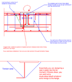
Depending how the overturning moment is introduced into the steel beam you'd need either stiffeners or anchors attached to the flange to prevent it lifting from the concrete. To me, you need a direct load path to transfer the tension from the overturning in the concrete, the best of which is anchor or rebar either welded or fixed with a coupler and bolt to the flange thats in tension. You could then design it as a simple baseplate with cast in fixings. Reo as required. Probably worth doing some kind of punching checks on the compression side if its large.
1733562619732.png
 
I thought you were originally talking about beams coming in at right angles to the concrete element and embedding with a moment demand, which is also what Koot drew. There is a design method for this in the Canadian Precast and Prestressed Concrete Manual that I've used for heavy equipment anchorage before.

Are these rails just to develop this moment resistance into the slab or is it there for something else primarily? Like, is this precision equipment that needs a levelling surface? It's a really weird solution if this is mostly here for moment resistance development.

People are talking about the breakout, but I've done lots of weird steel industrial junk and the part that's flashing bells for me is the wide flange. How are they getting load into it and how is it spreading load around? How is the item above anchored to it and how often? This is something that feels like it should be stiffened to hell and back unless the loads are basically negligable

There's all sorts of plate bending and torsion stuff here that is really not compatible with concrete breakout mechanisms.

1) How are they getting load into it and where do they think it's going. Their plan needs to match your assumptions for some of this stuff. like, if you think this is a bearing on one side with tension down the web to the bottom situation, then they need to have a load path to get there too. The load path when you're loading in this direction with bolts or welds tying in is pretty fiddly and you going off in one direction when they've detailed something incompatible ends up being a problem.

2) This wide flange isn't going to span torsion down the length of itself, so if these are discrete connection points to the superstructure them it's only going to provide anchorage into the concrete really locally to those points.

3) The bearing/breakout mechanism is what came to mind as an option with me as well, but I'd be really wary of parts of it without stiffeners because flange bending is going to come into play. Your bearing for the breakout cone might just be a couple of flange thicknesses wide, for instance

4) The lack of bar continuity ends up being weird from a confinement standpoint. I don't really like the tension mechanism without it, honestly. Draw out what that concrete breakout looks like if it's only happening on the tension side and it's only bearing a few tf past the web. You've got this little 12" thick piece of concrete being asked to do an awful lot and don't even have the redundancy of continuous bars through it to provide a bit of friction if that crack opens up. It doesn't feel great to meIt also sounds like this is potentially dynamic, which raises crack control concerns local to the rail that would need some bar continuity

5) If you're doing the bearing / tension couple thing, you probably want some vertical bars adjacent to the beam to drag the tension back down into your load carrying slab. If you have continuous bearing bars through your beam then I'd need to think about this a bit more, but if your slab below is the thing with spanning capacity then you need to get uplift down there unless the weight in the breakout cone is enough to fully resolve the moment.

Can you give an idea about the magnitude of loads? It makes a pretty big difference. I'd also be screaming for information on the detailing of the rail because what it looks like may answer a lot of questions above how it's supposed to be working.
 

Part and Inventory Search

Sponsor