Continue to Site

Eng-Tips is the largest engineering community on the Internet

Intelligent Work Forums for Engineering Professionals

  • Congratulations KootK on being selected by the Eng-Tips community for having the most helpful posts in the forums last week. Way to Go!

Bridge Crane Anchor Bolts Installed at Angle

Status
Not open for further replies.

ONT003

Civil/Environmental
Feb 23, 2017
6
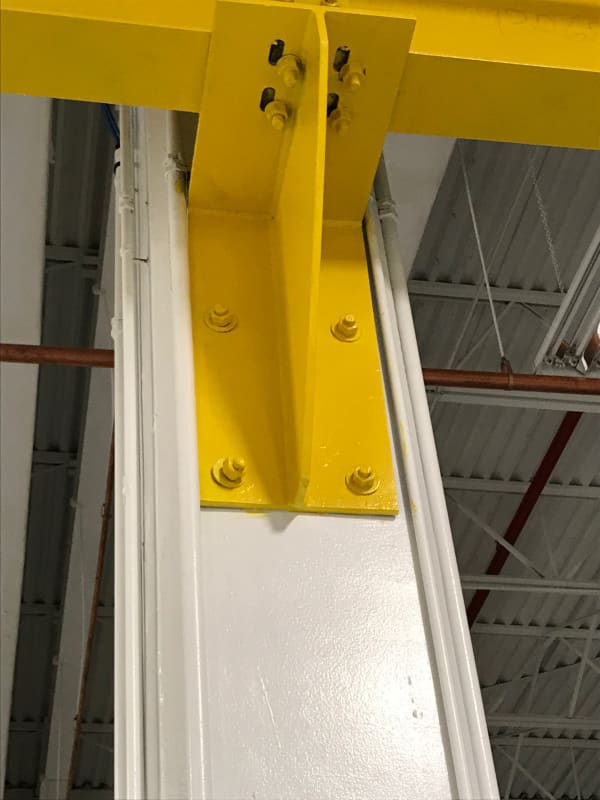
During weight test of a 1/4 ton bridge crane it was noted that one set of anchor bolts on one particular column were not installed straight and flush. The crane is anchored across 5 or so concrete columns, all other anchor bolts are installed correctly.

Should this be rectified before crane operation? Concerned with deformation over time. The shop is soon to be occupied and we don't have a structural engineer on board at the moment to evaluate. Please see photos. Thank you.

 
 https://files.engineering.com/getfile.aspx?folder=de68716f-6209-4058-8773-42f8b3a781ea&file=IMG_0813.jpg
Replies continue below

Recommended for you

This is utterly deficient, even by shadetree handyman standards; I can't even call it a joint connection.
Raise an non-conformance immediately and involve a structural engineer - go outside the company if you must.
After that I would enquire into the basic skills and qualifications of one or more members of your workforce. And where was QC?
Higher elevation, it appears that bolt fastening was an afterthought. Making bolted joints is based on science, and it requires procedures, tools and training to be successful (and above all, safe).

"Everyone is entitled to their own opinions, but they are not entitled to their own facts."
 
Loads due to the incline are likely small. Can you use a bevelled washer, so at least bearing and shear are somewhat normalised? You can recheck the shear and tensile component based on the sloped connection fairly easily.

Alternatively, the contractor can provide a sealed engineering report.

Dik
 
Good luck rectifying that abomination (there's no way I'd leave that as it is).

Dik said:
Alternatively, the contractor can provide a sealed engineering report.
Please provide feedback if you get that!
 
That's just hideous.

Are they even tight, or just spun on by hand.

Did you know that you can embed images directly by using the "Upload Image" tool.
IMG_0813_w61kem.jpg
 
OK, so the LOWER bolts are twisted and bent. Get a specific sealed, engineering approval for that.

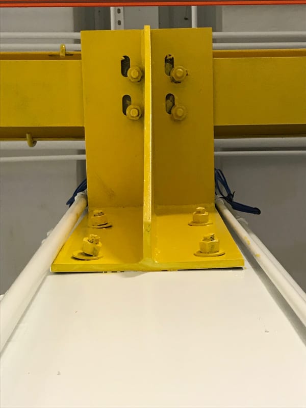
Get a SEPARATE engineering sealed letter approving the UPPER 4x bolt holes: All four new holes are burned out (not even drilled), covered with mis-matched non-structural washers, re-drilled away from the slots and original holes, and 2x of the 4x do not have wall thickness remaining to hold anything.

And this was found during the load test?
Are ALL other welds and supports verified correct?
Are ALL of the column-to-foundation bolts verified correct and with proper torque?
(I'd require the foundation bolts to be loosened and re-torqueed in your presence, since the physical workmanship demonstrated here is not worthy of a fifth grader.. )
 
Another angle thanks to the other poster's tip to Upload Image. Sorry if the other one skewed it, this is an overhead bridge crane support secured to the top of a concrete column.

Yes, it seems this renovation job was accepted by the contract executer. I was consulted by a user of the building. I will recommend verification and sealed engineering approval for all of it.

Thank you all for confirming my concerns!!
 
Remember that the bottom bolt is only predominantly in vertical shear. Just use a tapered washer and retighten the bolt if it concerns you. Otherwise I'm tending towards being not overly concerned, it happens all the time to avoid reinforcement.

I think steel standards allow some angle to the bolt before you need to consider tapered washers (not sure what it is off the top of my head), but this is probably more than would be acceptable.

If it was under tension I'd be more concerned as it makes breakout towards the edge more critical as induces a shear towards the edge in addition to the tension. I wonder why they never located the top bolts right at the top of the bracket to maximise the lever arm for the dealing with the moment.

If the crane is 0.25 ton SWL, then I can't imagine the loads are particularly high for a little baby crane like this? The fact that its been tested (I assume you tested each support?)as you noted should be enough to give you some confidence in it before getting to far into it. Or did you stop the test because of this?

If you must do something, throw another bolt in above the current one, an easy fix.

The bolts to the runway beam look like a bit of a shambles. I'd expect to see a plate washer welded to the bracket when the bolt holes are so far out like shown.
 
Agent666,
That's a little sanguine for my liking. A lot actually.
Deficient installations from the past that have not failed is absolutely no justification for permitting it on this or any other job.
The bolt installer should not know which bolts are more critical than others, nor how they are loaded.


"Everyone is entitled to their own opinions, but they are not entitled to their own facts."
 
Do my eyes deceive me, or is the web distorted?
Could that curvature be due to a load currently applied, distortion built into the anchor, or some other as-yet unidentified SNAFU?

It would be interesting to see how much that anchor "springs" when the weight is lifted and the nuts are removed when you replace it.

You ARE going to replace it... right???

No one believes the theory except the one who developed it. Everyone believes the experiment except the one who ran it.
STF
 
These appear to be post-installed anchors and they also appear to have been cut, so they probably do not have appropriate embedment....start over. Bad on top also.
 
Maybe I am just sanguine like Agent666, but I think some of you are being too alarmist.

Now if this is really just a 1/4 ton crane (and I have never experienced such a tiny bridge crane), the bolts are entirely adequate by inspection. The connection may be butchered, but it will do the job.
 
There is a difference when the angle is turned to the edge of the concrete column or to the inside part. When it's turned to the inside part, the basic problem is about embedment lost and of moment forces working on the edge of the wedge anchor rather than a simple tension force.
If we look at the direction of the wrong installed anchor, it's obvious that it's wrongly directed. It means that the concrete edge failure will be much much lower for this particular anchor and since the way of calculating anchor is to use the weakest link and multiply by the number of anchors you can understand that the situation is not correct from the start especially if it's working on shear forces. But even on tensile forces, it looks like the end of the anchor is really on the edge of the concrete column which means the concrete cone force will be also much lower. And we don't speak about the fact it's a cut wedge anchor, so , from the start it's to short, and that it's installed with an angle of about 45 degrees, so, it's also much less deep than request...
So, that's a few of the reasons why this installation is completely wrong and should be removed and reinstalled (and check the other wedge anchors, if some are cut, you should also reject them).

Now, if you had a similar situation, with only shear forces, and with wedge anchors installed in the direction opposed to the edge (so that the end of the anchor would be further than if it was installed as it should be), then, the situation is completely different because basically, for shear forces you don't always really "need" the whole embedment depth to get the whole shear forces and, since the end of the anchor won't be closer to the edge, the reduction factor due to a bit lower embedment depth on one on four anchors shouldn't be decisive, it would perhaps reduce by 10% the capacity of one anchors on 4,about 2,5% of your entire connection...

If you got a similar situation with only tensile forces, and again a wedge anchors far from all edge or with an anchor installed towards the inner part of the column, if it's not cut, but just installed in a slightly lower depth, you can weld the part of the anchor not in contact with the profile (to avoid any moment on the edge of the anchor), and if the depth, because of the angle of installation is about 2 cm less, again you got a situation with one anchor with lower tensilve concrete cone capacity of about 15-20%. It could be acceptable even if it's not ideal. Understand that when a contractor is meeting a rebar on field, it's easy for us to explain why he has to install the wedge anchor straight but it's not always possible... then it could be the "less bad solution" and not a crucial load reduction for the connection (let's not forget that the concrete cone calculation is a very conservative one and don't take in account much of the rebars in the concrete, which means that usually, the real capacity is much higher than the calculated one)...

So, the main point about refusing anchors wrongly installed, is to understand the influence on the capacity of the connection. In your case, you should obviously require to remove all the cut wedge anchors and all the one installed in the direction of the edge.

If the contractors tells you that there is a rebar just on the spot of the wedge anchor, he should first, refill the hole drilled until the rebar with chemical anchor (the cheapest injection one you can find). Then drill a hole in the direction of the center of the column in the smallest angle possible. and then weld the "upper side" of the wedge anchor to the profile to avoid any moment on the head of the wedge anchor.

Good Luck
Regards
Eng. Yves De Lathouwer
Head of the Engineering Department
Adit Ltd
 
hokie66...I rarely disagree with you! In this case, I go to my experience in failure investigations....

The crane is a dynamic structure. All of these connections are subject to load reversals and fatigue from repetitive loading. At the risk of being alarmist, I have seen so many times that contractors install wedge anchors and can't get them in without obstruction, only to install them with poor embedment, compromising both shear and tension capacities. Yes, the lower bolts have little tension applied; however, they have some. The angled placement is indicative of poor QC on the part of the contractor. How many other places has he/she compromised quality? Though shear capacity of wedge or similar anchors is less dependent on embedment than the tension capacity of same, it still plays a part.

A single event load test for dynamic structures is inadequate. Properly done, the load test should include dynamic strain gauges so that load event frequencies can be developed.

Granted, the connection is lightly loaded, but a 1/4 ton capacity crane will often get overloaded....yes, it can be overloaded and still perform.

Will this connection perform under normal service conditions? Likely yes. In the event of a failure (either structural or serviceability), will this connection be a focus of attention? Without question, yes....simply because of the poor QC of the contractor.

Can this condition be remedied without removing the connection? Yes. As Agent666 noted, it is likely as simple as installing another anchor.

Not being alarming, just realistic with what happens when things go to $h1t.
 
hokie66 said:
Now if this is really just a 1/4 ton crane (and I have never experienced such a tiny bridge crane), the bolts are entirely adequate by inspection. The connection may be butchered, but it will do the job.
How do installers differentiate between "just a 1/4 ton crane" and something more 'critical'?

How often have you heard "it's just a small weld". Fun fact: the smallest welds are the most problematic.

I also do failure analysis. Fasteners are my most popular class of mechanical failure. However I prefer that there be no injury or loss of life associated with a failure.


"Everyone is entitled to their own opinions, but they are not entitled to their own facts."
 
You as the engineer can/should differentiate, back in the day engineers used to use judgement backed by some appropriate calculations, now not so much.

The detail has some capacity, obviously not as much as it being installed perpendicular, but most likely adding another bolt for piece of mind absolutely kills it.

I suspect if that one bolt fails and the loads are low enough as seems to be the case then the other 3 will still kill it. Sorry for the engineering judgement [thumbsup2].
 
Agent666.....I agree. The only issue is that in the event of a failure, such poor QC focuses the failure here, rather than perhaps somewhere else.
 
Status
Not open for further replies.

Part and Inventory Search

Sponsor