Eng-Tips is the largest engineering community on the Internet

Intelligent Work Forums for Engineering Professionals

Buckling lengths for columns next to a lower non-sway frame 2

nivoo_boss

Structural
Jul 15, 2021
130
0
16
EE
Hey everyone!

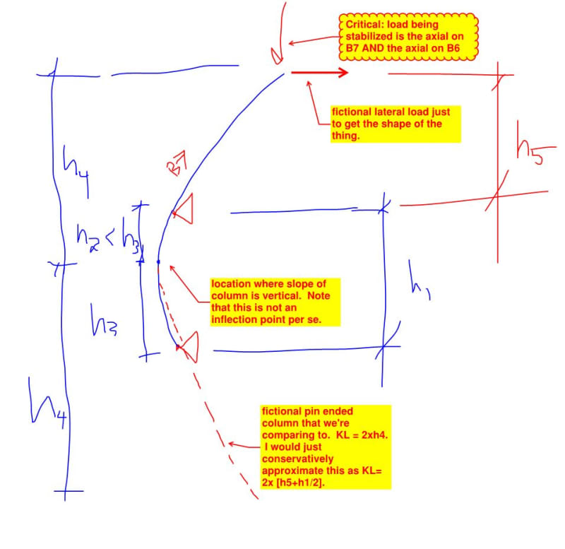
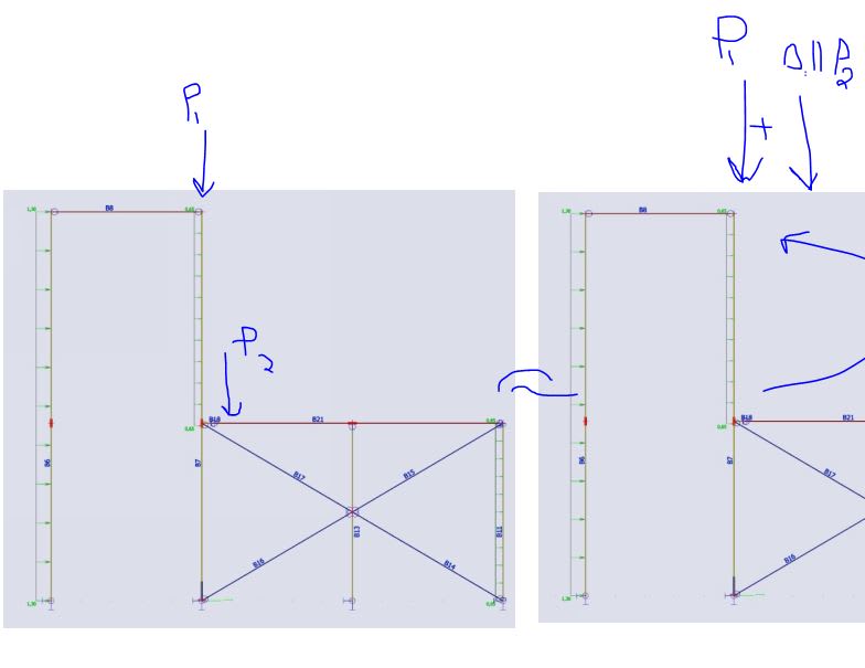
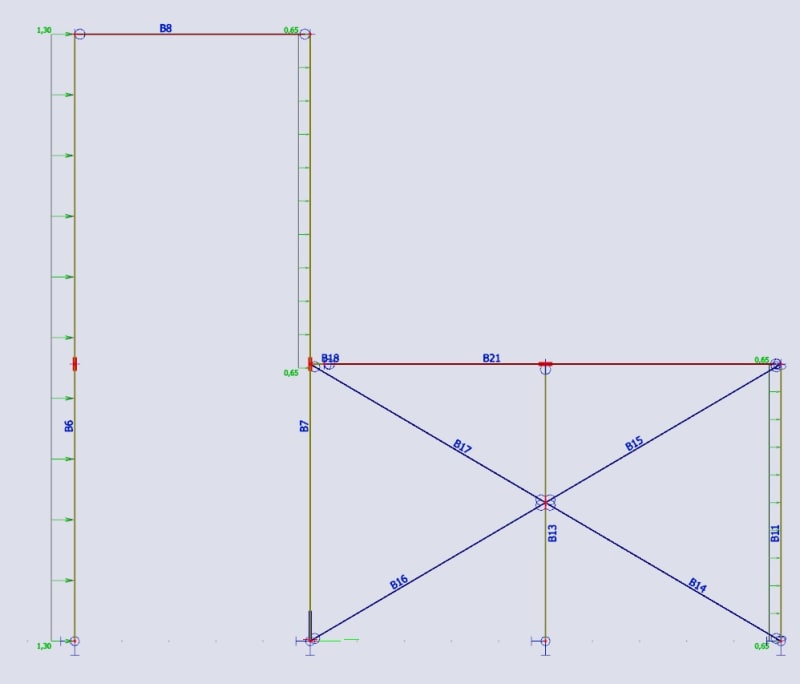
What the buckling lengths for member B6 and the top half of B7 should be? All supports are pinned and currently connections between the beam B8 and its columns are pinned as well. B6 is about 13 m high.

frame-buckling-lengths_pzaden.jpg
 
Replies continue below

Recommended for you

Lateral torsional buckling? Because no axial compression in B6 and B7. If you mean for a different load case where B8 is loaded then it depends on design method.
 
Some methods take K=1 always so buckling length equals member length. But you're asking what is the buckling length so I guess you're using effective length K>1 method. For this frame I would use a K=1 method which usually means additional lateral loading and nonlinear analysis. Check code if this is an option. Otherwise the B7 effective length isn't so simple plus you need to keep track of B6 load causing B7 to buckle. See the US direct analysis method. Australia is basically the same but not a free code and has no literature. US code is free and has lots of supporting literature.
 
I agree that this is a good example for a nonlinear check. However, I'd like to do a quick hand calculation in this case to know what I'm expecting.
Maybe I'm way off here, since this is not my strong suit, but I'd expect B6 to behave as a pinned column (buckling length = height of the column) and for global stability I'd move the vertical load and horizontal point load (top reaction) from B6 to the top of B7. Then I'd expect B7 to behave like a beam with cantilever... I'd expect the inflection point to be about 15 - 20 % under B21, but you could also calculate it. So I guess that for the top part of B7, buckling length would be 2*(upper span + 20% of lower span)
As I said, this would be only to get the idea what to expect from software.
 
Agree with Hardbutmild for the hand check but I would take half the backspan for B7 effective length. I don't like it though because the diag brace puts extra compression in the lower end of B7 so it might be close to buckling itself and offer no resistance to stabilise the top end.
 
See below for:

1) What I consider the most accurate KL to be done by hand.

2) The approximate KL that I would normally use instead.

3) The most important part: recognizing that the axial load applied to B7 needs to include the axial load on B6.

c01_yjotvv.jpg
 
This is not well suited to simplified approaches. Industrial frames like this aren't what the effective length procedure is predicated on. You also have a small number of columns, another strike against it.

Effective length (and the Direct analysis method) was/were developed for buildings, this looks like some kind of almost aircraft hanger bolted to a braced frame. The approach is perhaps valid, but I'm not fully convinced plowing into it immediately is correct. I think this needs to be vetted somewhat before trying to apply the approach.

What KootK is suggesting has merit, particularly as a way to "bound" the solution in a precautionary sense.

I would imagine treating this as a sway frame and neglecting the braced frame would be another bound for that, in that it probably would be conservative to at least four out of five dentists to treat it that way.

This looks more like an Abaqus problem to me. Not a huge fan of the "everything is pinned" analysis depicted, too.
 
Kootk said:
See below for:

I just checked this using h5 = 7, h1 = 6 and it comes out pretty close.

An euler buckling analysis gives effective length factor (k factor) = 2.59 x h5.

your first method gives k factor of 2.7

You h1/2 method gives k factor of 2.85

In any case the cantilever effective length is significantly longer than the twice the cantilever length.
 
KootK said:
See below for:

1) What I consider the most accurate KL to be done by hand.

2) The approximate KL that I would normally use instead.

3) The most important part: recognizing that the axial load applied to B7 needs to include the axial load on B6.

I've very impressed with this approach. It might be effective length 101 that I was asleep in class for, but either way it has added to my knowledge base. Like Tomfh I checked you logic and it was extremely close and slightly conservative to the software** output which I use which calculates effective length from Euler buckling.

**I'm quite dependent on software for many things, but I don't follow it blindly. I very much appreciate simple, logical hand calcs.
 
Good work Kootk and Tomfh. Just want to tack on how right hand side loads affect column B7. If beam B21 or brace B17 loads are big enough to make bottom end of B7 buckle then no capacity for load at top of B7. This is same as top end of B7 has eff length of infinity. So eff length goes from Kootk and Tomfh numbers for no right hand load to infinity for big right hand load. US direct analysis will look after this for you.
 
Smoulder said:
US direct analysis will look after this for you.

So will the K-factor method. Using tomfh's example, you would move the low beam load up to the cantilevered column tip and scale it down by [(6)^2 / (2.59 x 7)^2] = 0.11. And this is what I would have expected a well trained engineer to do before the advent of commercially available FEM. It's not as though they just turned a blind eye to things like this back in the day.

In addition to solving the problem, this method makes it very apparent to the designer how much of a difference the load at the low node will make. The answer being not much unless it's a very large load.

In practice, I would usually do the reverse of this by moving the cantilever tip load down to the low node and scaling up accordingly. That would allow you to preclude the non-buckling failure modes without having to consider two design cases.

c01_rui7t3.jpg
 
Back
Top