Continue to Site

Eng-Tips is the largest engineering community on the Internet

Intelligent Work Forums for Engineering Professionals

  • Congratulations KootK on being selected by the Eng-Tips community for having the most helpful posts in the forums last week. Way to Go!

built up beam 2

g.n

Structural
Apr 5, 2024
4
Hello, I am designing a built-up beam with several I shapes and was wondering if anyone knows about a reference or would like to share their experience with these types of members. The beam should span 40 ft and will be subjected to biaxial load.
 
Replies continue below

Recommended for you

I'll be surprised if you are able to find a reference particular to that situation. Probably a first principles or FEM thing (shape builder software, github stuff). I feel as though @Celt83 keeps fairly abreast of the options these days.

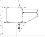
A good place to start would be to post an image of the kind of cross section that you're contemplating. Sometimes there are marvelous simplifications that can be employed to great advantage. It's impossible to discuss that meaningfully without knowing what we're dealing with however.
 
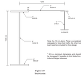
The section is for a head block beam. The attached image comes from a Modern Steel article similar to my case. I have an idea of what I need to do but wanted to make sure I am not overlooking anything.
1733875085661.png
 
Could you point me/us to that MSC article?
 
its just a beam, no?
calculate section properties
apply loads
calc local bending moments; determine stresses at extreme fibers and stresses in flange sections
calc local shear loads; determine shear flows in each part of cross-section; this can be hard with a complicated cross-section as shown above; see aircraft multibox shear flow examples; determine shear stresses in each part of section
check beam deflections
check local buckling in flange and web sections
check beam lateral/torsional buckling
check connections at ends
 
Could you point me/us to that MSC article?
The article can be found here:
its just a beam, no?
calculate section properties
apply loads
calc local bending moments; determine stresses at extreme fibers and stresses in flange sections
calc local shear loads; determine shear flows in each part of cross-section; this can be hard with a complicated cross-section as shown above; see aircraft multibox shear flow examples; determine shear stresses in each part of section
check beam deflections
check local buckling in flange and web sections
check beam lateral/torsional buckling
check connections at ends
Thanks for the checklist I will look into the shear flow examples. Do you know of a reference I can consult?
 
Without much understanding of the problem you're trying to solve, my first thought would be to look at it as two separate beams with one resisting vertical loads and the other (sideways beam) resisting lateral. I want to say this approach would be conservative, although it's such an odd section shape that I'm not convinced there wouldn't be some problematic warping/twisting action going on.
 
You might find help in crane beam design resources. They are usually some type of built up section due to the need for strength in both directions. Crane-Supporting Steel Structures by R.A. MacCrimmon is a great resource with design examples. You can get it free. Just google Canadian crane guide.

1733948501313.png
 
The article can be found here:

Thank you. I think that I understand the situation now. I would say that your primary concerns are:

1) Enough lateral strength and stiffness for any lateral loads. Hence the big beam on its side.

2) Enough vertical strength and stiffness for any vertical loads. Hence the big upright beam in the middle.

3) The above are pretty obvious. I would say that the primary reason for the particular configuration of these things is creating an unbraced member that can span a very long way without laterally torsionally buckling. I think that this is why you see:

a) The pair of vertical beams spaced out a bit.

b) Intermittent diaphragm plates connecting the two upright beams.

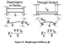
Research twin girder bridge buckling and I suspect that will uncover the lion's share of what is non-standard about the design of your head block thingy. Here's one resource from the bridge world: Link

c01.JPG
 
Last edited:
or shear flow due to torsion loading Google "multicell wing box shear flow" --> lots of links, for instance

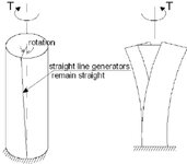
There is no meaningful shear flow due to torsion here. This isn't a cellular / st venant thing. Rather, it's predominately a version of warping torsion.

A simple, right sized solution here will be:

1) Design the horizontal beam alone for lateral load assuming that it's fully braced torsionally.

2) Design the middle, vertical beam alone for vertical load assuming that it's braced torsionally at each diaphragm pate.

3) Design the left beam and its connections to provide the requisite warping torsion stiffness to preclude LTB. Yura is your friend.

4) Any plausible stitch welding between the horizontal and vertical beam will be gross overkill. Sure, bust out some VQ/It on the composite section if you're feeling fancy and getting paid by the hour.
 
well, it depends on the loading and how the beam is attached. there is nothing on either in the original post.

I don't disagree with your approach KootK.
 
well, it depends on the loading and how the beam is attached.

Truly, I don't believe that it does depend on the loading or how the beam is attached.

The combined shape will respond to torsion primarily by throwing one beam upwards and the other beam downwards. Just like the flanges of a torqued wide flange section when it warps.

I realize that you are a pretty sharp cookie when it comes to mechanics of materials stuff. And we're all grateful for your contributions here. That said, I feel that your aerospace bias leads to you sending our guys off on wild goose chases at times. And this is one of those times in my opinion.

Boeing might be willing to pay their people for a multi cell, wing box, shear flow analysis.

Walter P Moore is going to give their people 15min and, maybe, a Styrofoam cup will some bad coffee inside.

c01.JPG
 
Thanks KootK! Your comments were spot on and exactly what I was hoping to hear. Also, thanks SWComposites, I’ll take a look at shear flow as it might be useful later
 
Also, thanks SWComposites, I’ll take a look at shear flow as it might be useful later

I checked it out and it is pretty cool, even if it's not the path forward here. I've tinkered with similar problems in regards to concrete shear wall assemblies that form multi-cellular arrangements. It gets complex in a hurry unless one is willing to bust out a little soap film analogy voodoo. Of course, the kids are just calling that FEM these days.

c01.JPG
 

Part and Inventory Search

Sponsor