Continue to Site

Eng-Tips is the largest engineering community on the Internet

Intelligent Work Forums for Engineering Professionals

  • Congratulations KootK on being selected by the Eng-Tips community for having the most helpful posts in the forums last week. Way to Go!

Bushing connectors in beam element joint - load transfer

Status
Not open for further replies.

BragiBaldursson

New member
May 5, 2021
30
How do you model 2D beams (doubler and skin) and fasteners connecting them using bushing connectors in Abaqus?
 
Replies continue below

Recommended for you

Can you provide a simple scheme or picture showing what you want to model ? Are you talking about beams consisting of two layers bonded with adhesive ? What exactly would you like to connect with bushing ?
 
Abaqus has fastener elements that can be located anywhere, they do not need to be at node locations. Mesh the plates with shell elements, add the fastener elements at the fastener locations. Bearing loads come directly from the fastener element output.
 
We model the doubler and skin using B21 elements (3D deformable, linear analysis). Loads and boundary conditions are as applied in the figure
loads_and_bc_tkfahh.jpg


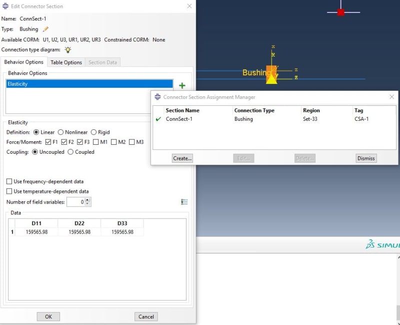
We define a bushing connectors between the doubler and skin at the fastener locations with these properties (spring stiffness 159565.98 lbf/in - inverse of Swift fastener flexibility).
connector_r4qm2q.jpg


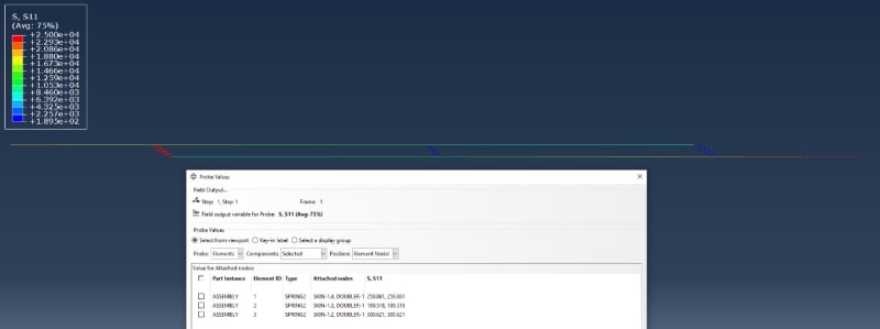
These are the results for the fastener bearing loads and they are way off
results_yruhjd.jpg
 
BB -
Hmm, that looks odd.
I would have modeled the straps with plate/shell elements, rather than beams, but it still should work with beams.
I would have also put several nodes between each fastener and between the end fasteners and bc's and loads.
I would also make the nodes coincident, rather than offset. It is strange that the bottom picture seems to show bending. Must be due to the node offsets.
Are the two straps the same material/thickness? If not, I would start with identical straps, and then the end fastener loads should be exactly the same.

SW
 
The beams have cross section just like a shell and will exhibit the same stiffness. If using MyStran bushing it makes sense to put the plates coincident as the bush element in Mystran is a 1D spring acting in the X direction. This bushing is 3D. The straps are 0.04 and 0.05 inches. More elements will not make a difference.
 
We got it working using truss elements constrained to move only in x direction and springs with only stiffness in x direction.
IMG-20220112-WA0001_nmnlg9.jpg
æ
 
Status
Not open for further replies.

Part and Inventory Search

Sponsor