Continue to Site

Eng-Tips is the largest engineering community on the Internet

Intelligent Work Forums for Engineering Professionals

  • Congratulations KootK on being selected by the Eng-Tips community for having the most helpful posts in the forums last week. Way to Go!

Cable Btm Chord Truss

Status
Not open for further replies.

bigmig

Structural
Aug 8, 2008
386
I'm looking for some help in someone pointing me in the right direction of a supplier
who deals in architectural grade cables, clevises and cable attachments. Someone who can
supply a CABLE (not a rod) for a truss like this......(see attached). Thanks in advance.
Preferably in the continental US.
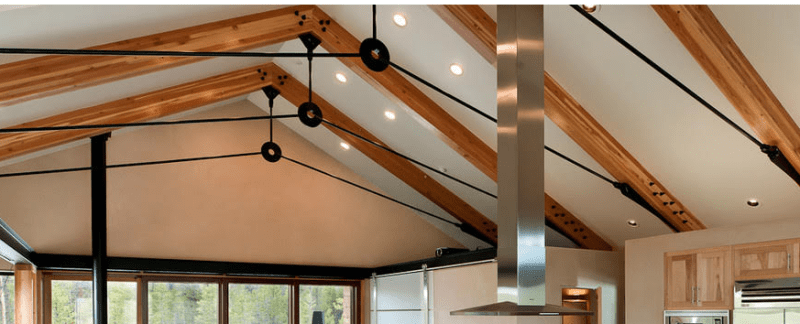
Capture_e1ecih.png
 
Replies continue below

Recommended for you

Bigmig:
Despite your protestations to the contrary, cable (wire rope) is not the best material for this bottom chord. Cable has too much and somewhat uncontrollable linear elongation under tensile loading. While a solid steel rod has better controlled elongation vs. tensile stress characteristics. The improvement in structural performance far outweighs any appearance changes and the hardware for a rod is certainly no more complicated or expensive. There is also some movement in the bolted connections at the truss bearing ends which has to be taken up in adjusting these trusses to their final configuration. In effect, you need a turnbuckle or left/right threaded coupler at each bearing end to tighten the threaded rod and bring it into play in supporting the rafter members. That’s a nice looking vaulted ceiling, but not quite as simple as you think.

 
Agree with dhengr. Another thing to consider is that the rods won't help at all in uplift.
 
hokie66 said:
Agree with dhengr. Another thing to consider is that the rods won't help at all in uplift.

Yup. Seems like the only option would be to somehow create enough fixity at the ridge connection so that the top chord can span wall to wall. Probably only practical if the net uplift is really low. Maybe use a cantilevered steel column to resist the thrust forces? I kind of wonder in that picture if they have some sort of buttress system with the interior walls or they’re just not even considering uplift. From what I’ve seen, it’s seems common for custom residential designs (outside of high wind areas) to give very little consideration to uplift beyond calling out hurricane ties on the rafters. And to be fair, it’s almost impossible to track down every uplift load down to the foundation with they way these things are constructed.

In regards to the bottom chord, I’m not sure what you mean by architectural grade cable. Wire rope pretty much all looks the same, I guess maybe they can put a coating on it? Macalloy produces every nice stainless steel rod bracing and connections for exposed conditions, and you could probably get away with a small enough diameter where it’s pretty much the same as a cable. That said it’s pretty pricy. I’ve speced it on a few jobs where it ends up getting subbed out for standard round bar, and if your painting it powder black you might as well just use that.
 
Because of the nonlinear cable behaviour and the fact that they don't behave elastically except at low levels of loading relative to ultimate capacity as dhengr alluded to, for a given cable you might be designing with very low utilisation so this doesn't cause an issue. So substituting a rod could result in a smaller rod (if structural steel) compared to a cables diameter for the same extension criteria.

If cables are your thing, then perhaps you could look at marine suppliers as wire rope used in yachts and so forth may have similar connections for rigging?
 
I am still wrapping my head around how this system works. With all 3 cable members being tension only members, I am seeing the roof could resist uplift, but not as a traditional truss. I have never designed one of these, but let's look at what might happen.

Under Gravity loads, the exterior walls try to move outwards. This pulls the diagonals in tension away from the 'doughnut". The diagonals want to lower the doughnut, but the vertical tension member keeps that from happening.

Under wind load, the wood rafters want to go up. The uplift on the rafter pulls on the vertical cable that tries to lift the doughnut. To lift the doughnut, you must put the diagonals in tension and the walls try to move inwards rather than outwards. The ability to keep the walls from moving inwards is where I see the question mark to be in what I am seeing. I wonder if the roof is heavy enough to prevent uplift?

And lastly, are these prestressed to some degree by design?
 
Ron, if you think of it as similar to a scissor truss, does that help? Anyway, if the uplift overcomes the gravity load, it won't be by much, and it will be a short-term load, so the lateral bending resistance of the top plate of the walls is probably sufficient for the lateral thrust. If it was my design, I would check it and be sure it was adequate. It wouldn't be difficult with a configuration like that to bump the top plate to a 2x6 or 2x8, if required.

As far as the lateral spreading under gravity loads, I would approach it by compensating for it in the length of the rods, so that it's pinched a little initially and assumes the proper final shape with the roofing on. Then you just wait until after the roofing is on before locking it into the walls, probably using a slotted connection of some kind. Alternately, there may be some adjustment mechanism in those connections. It's hard to tell from the photo.
 
Status
Not open for further replies.

Part and Inventory Search

Sponsor