Continue to Site

Eng-Tips is the largest engineering community on the Internet

Intelligent Work Forums for Engineering Professionals

  • Congratulations MintJulep on being selected by the Eng-Tips community for having the most helpful posts in the forums last week. Way to Go!

Cable damage - Circuit Breaker Selection in NEC/IEC

Status
Not open for further replies.

NickParker

Electrical
Sep 1, 2017
420
In British Standards, the standards make ensure that the circuit breaker is selected such that it trips before the cable gets damaged. How this is ensured in NEC / IEC standards?

British Standard Cable sizing: (BS 7671)

Ib <= In <= Iz; and I2 <= 1.45 Iz

Iz - The current carrying capacity of the cable for the particular method of installation.
It - The tabulated current for a single circuit at an ambient temperature of 30°C.
Ib - The design current - the actual current to be carried by the cable.
In - The rating of the CPD, (Fuse or MCB).
 
Replies continue below

Recommended for you

You have a similar equation in the IEC world. And the objectives are the same. The equation you give above does not address short circuit scenarios as it only refers to relay pickup and not the actual trip time, which is the crucial parameter. In essence, you would need the cable damage curve and then ensure that your total trip time is below the time taken for a cable to get damaged for a given fault current.
 
Below is an example of a TCC coordination curve shown cable damage curve protected by a CB usually used in the NEC/IEEE Marketplaces.

TCC_Cable_Damage_Curve_qgplxs.jpg
 
BS 7671 Regulation 433
The current I2 is causing the effective operation of protective device.
What it happens when the actual current it is more than Iz but less than 1.45*Iz ?
NEC 240.4 Protection of Conductors.
Overcurrent Devices Rated 800 Amperes or Less: the device rated current may be more than conductor ampacity[ in some conditions].
Overcurrent Devices Rated more than 800 Amperes the rated current shall be less or equal to the conductor ampacity.
(G) Overcurrent Protection for Specific Conductor Applications.
Overcurrent protection for the specific conductors shall be permitted to be provided as referenced in Table 240.4(G).However, it is about the conductor required ampacity and not to the overcurrent protection setting.
No reference of the current causing the effective operation[I2].
However, it seems to me, if the device is UL tested and approved no one will care how it works, if it is according to NEC.

 
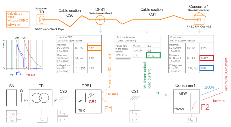
The choice of cables and protective devices for them is a complex procedure, and in fact, to select cable cross-sections + circuit breaker correctly, you must calculate not only actual load current but also the short-circuit currents in two points: at the end terminals of the protective device (maximum SCC – to select breaking capacity) and at the main bus of a consumer (minimum SCC – to determine disconnection time).
You can use:
[ul]
[li]the IEC 60364-5-52 standard to define installation methods and current carrying capacity of power cables;[/li]
[li]the IEC 60364-4-41 standard to determine the maximum disconnection time for TN and IT systems;[/li]
[li]the IEC 60947-2 standard to check the breaking capacity of the protective device;[/li]
[li]the IEC 60909 standard to calculate maximum and minimum short-circuit currents;[/li]
[/ul]
You need to make sure that the disconnection time provides protection against indirect contact at the consumer and to properly select breaking capacity and making capacity of the circuit breaker.
The voltage loss from transformer up to the main bus of a consumer also shall be calculated. See the scheme of calculations in the attached files.

I use the free CAD-plugin MeteorSpec to make the network model and calculate all necessary parameters.

MeteorSpec_scheme_of_calculations_prjj8d.png


In addition, short-circuit thermal withstand of the cable must be checked. Disconnection time of the circuit breaker must be small so that the allowable temperature limit of the cable will not be exceeded.
 
O.K. Juan you explain us how to calculate Iz according to IEC 60364-5-52 for low voltage. For medium voltage I think IEC 60502-2 Annex B is indicate [however, informative only].
What about Ib and In? As far as I know IEC 60364-4-41 does not deal with overload but only with short-circuit currents.
In IEC 60972-2 only Ir [Adjustable overload setting current] is stated [it could be close to In?] and Ir*1.3 as Conventional tripping current [I2?].


To 7anoter4

IEC 60364-5-52 contains tables of cable current ratings, with corresponding conductor temperature, ambient temperature and soil temperature + various derating factors.
There is a website where data on LV cables is collected (from IEC 60364-5-52, BS 7671, NF C 15-100 and AS/NZS)
[URL unfurl="true"]https://wiki.openelectrical.org/index.php?title=EPR/XLPE_Current_Ratings_(Copper)[/url]
In my opinion, everything is described in great detail there.


I do not know the IEC where exact methods for calculating maximum actual load currents (design currents) for indoor installations and\or LV distribution networks would be given. These techniques are collected from various sources.
The software I use allows calculate actual power demand and design currents usng correction factors (the factor of maximum utilization Ku and the factor of simultaneity Ks) for each feeder of LV distribution network. [URL unfurl="true"]https://meteorspec.com[/url]/


Yes, I gave an incomplete list in my previous post. The IEC 60364-4 consists from: Section 41: Protection against electric shock; Section 42: Protection against thermal effects; Section 43: Protection against overcurrent.
 
7anoter4 said:
What about Ib and In? As far as I know IEC 60364-4-41 does not deal with overload but only with short-circuit currents.

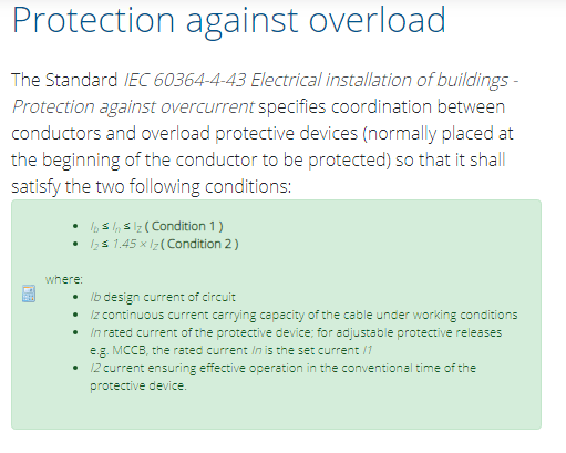
The link Link says it is mentioned in IEC-60364-4-43.
IEC-60364-4-43_xwrajl.png


Is there any relation between the nominal rating of the protective device and the selection of cable in NEC? Yes, I'm talking about the small/temporary overloads which exceeds the nominal rating of the protective device.

However, when I see the examples of cable sizing done as per IEC (Previously done by others/from internet), the conditions mentioned above in IEC 60364-4-43 are not followed but I could see these conditions are followed in the cable sizing done as per BS 7671.

I wonder if these conditions are indeed mentioned in IEC 60364-4-43, why is it not followed? (I have seen dozens of examples of cable sizing done by others as per IEC, but none used these conditions)
 
Sorry, I didn’t have time to finish my previous post correctly.

According to IEC, the protective device of a low-voltage feeder must provide two basic protections:

P1. the protection of people against indirect contact (obtained by a specified disconnection time of an overcurrent cut-out device combined with an earthing);
P2. the protection of cables and other equipment against overcurrents and against thermal effects, followed by the overcurrent (obtained by a protection against overloads and short-circuits).

Both items are of equal importance, but the P1 is usually more difficult to fulfill (especially on long lines). Therefore, the main attention when choosing a protective device should be paid to the IEC 60364-4-41 standard (Section 41: Protection against electric shock). The calculated minimum short-circuit current at the end of the protected line allows to verify disconnection time of protective devices. Maximum disconnection time is 5 sec or 0.4 sec for TN (400/230V).

Protection against overcurrent by IEC usually does not cause difficulties. But what I often saw from the wrong one is choose of breaking capacity of MCB. This is strange because calculating the maximum SC-current at the end terminals of MCB is not very difficult (usually it is 3-phase SCC).

So, when designing in IEC standards, the electrical designer has to do more calculation work than others.
 
Status
Not open for further replies.

Part and Inventory Search

Sponsor