Continue to Site

Eng-Tips is the largest engineering community on the Internet

Intelligent Work Forums for Engineering Professionals

  • Congratulations KootK on being selected by the Eng-Tips community for having the most helpful posts in the forums last week. Way to Go!

Cable Guardrail Design 4

Status
Not open for further replies.

dik

Structural
Apr 13, 2001
25,675
Does anyone have a reference for designing guardrails using 3/16 stainless steel aircraft cable as noted below. Properties of the cable will be determined.

The total length of cable is 50'-60' horizontal. The cable is supported by posts at 4' o/c vertical and the cable passes through the posts without hinderance (or friction). The cables are anchored at the ends by posts. The cables are located at 3" o/c horizontal. The cable spacing must prevent a 4" dia sphere from passing. I'm looking at determining the tension required to prevent passing of the sphere. Can anyone suggest a paper?

-----*****-----
So strange to see the singularity approaching while the entire planet is rapidly turning into a hellscape. -John Coates

-Dik
 
Replies continue below

Recommended for you

Thanks Deker! Key quote for me:
CTC Study said:
While reviewing the climbable guards area of study, the CTC narrowed the demographics of the population to children 4 years of age and younger. It was concluded early on that children 4 years of age and older could climb any guard with a height of 42 inches or less -- even solid walls.

Seems children can effectively do a muscle-up from the top rail @ 42".
 
The cabling is not readily accessible and is mostly an architectural design item. It's not a matter of climbing the strands; there is a 'table top' over them. I've decided to design it as a 'picket' load just to prevent the 4" sphere from passing if the spacing increases. If you're ingenious, you could likely get a 4" sphere through it, but it would be difficult.It's not a matter of tensioning the cable to provide this resistance, else the end posts are loaded too much. I just wanted to provide some resistance.

Thanks Decker... good reference to have.

-----*****-----
So strange to see the singularity approaching while the entire planet is rapidly turning into a hellscape. -John Coates

-Dik
 
BrigeSmith said:
An infinitely long cable can't be manufactured, either. No need to be argumentative over semantics. Ok, how about the longer the cable, the less the tension in the cable changes when the cable deflects at one point for the sphere to pass through? Does that make you happy? Anyway, the length of the cable is one of the parameters in the equation that was ultimately derived and calibrated to the test results.

Of course, friction between the cable and sleeves where it passes through the intermediate posts isn't accounted for, either, so it's not going to be perfect. No engineering model is ever perfect.

I still think using the results of the testing provides a good approximation of the tension the OP will need to design for in order to satisfy the criteria.

"Does that make you happy?" Sounds like it makes you happy

I'm not seeing where they specified a value for Lct in the calculations.
Regardless, I think this is a great exercise and gives us some wishful thinking numbers to put on a drawing.
My guess is this is all about keeping baby's heads from getting entangled in the railings. Can a baby put more than 8 lbs of force on the cable? - probably
How loose will the cables be once kids stand on it and turn it into a catenary?
Are these things ever tensioned to spec and how do they check that and who enforces it?
For a typical HSS 1 1/2x1 1/2x1/4, 42" end baluster and 200lb cable tension @ 3.125 in O.C., the deflection is over 1/4". Seems like they would be playing whack-a-mole trying to actually ensure all cables are tensioned correctly.

Anyhow, Happy Friday


XR250 said:
I'm not seeing where they specified a value for Lct in the calculations.

It's in Eq. 2, and defined directly below it:

LCT is the entire length of the cable between fixed ends.

For a typical HSS 1 1/2x1 1/2x1/4, 42" end baluster and 200lb cable tension @ 3.125 in O.C., the deflection is over 1/4". Seems like they would be playing whack-a-mole trying to actually ensure all cables are tensioned correctly.

Probably. This would likely require the end baluster to be larger or braced.


Yup... thanks.

-----*****-----
So strange to see the singularity approaching while the entire planet is rapidly turning into a hellscape. -John Coates

-Dik
 
At the beginning of Section B, (Page 10) it states they used 48 inches in the calculations, to match their test configuration.
 
Honestly, I still do not see where they show the value for Lct
 
Is there an easy method to put a preload into the cable other than going from a snug (no/small) load using the extension calculated from using a turnbuckle adjustment.

-----*****-----
So strange to see the singularity approaching while the entire planet is rapidly turning into a hellscape. -John Coates

-Dik
 
Yes, cable railing can be such a can of worms. Years ago I went down this path and came across information found online. I thought I had more information but this is all I could find from a project we did over 15 years ago. Hope it can help.
RSB
 
 https://files.engineering.com/getfile.aspx?folder=ee26b617-0a4f-45be-ac26-ef104f2af31f&file=Railing_Calculations.pdf
If you're doing a one off it may not be reasonable, but cable tension gauges are pretty available these days. We use them for things like overhead lines regularly. Looks like there some moderately priced ones for guardrails and similar. They generally work by laterally deflecting the cable in a controlled way and seeing how much it moves for a given force.
 
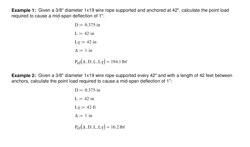
This is what I was getting at with BridgeSmith. Big difference if the cable is 42" between anchors (Lct) versus 42 ft. using 42" balluster spacing.
cable_llflgo.png
 
XR250 said:
Big difference if the cable is 42" between anchors (Lct) versus 42 ft. using 42" balluster spacing.

Nobody was arguing that point (and it would be silly to do so, since it's an obvious conclusion), but again, the total length of the cable is one of the parameters in the calculations in the paper linked to by Deker. The examples you posted would seem to agree with the conclusions in the linked paper.
 
Oof - I think this one went WAY off the rails on the sphere. The sphere is strictly for sizing of openings (at least in the US) and the designer is not intended to try and ram it through. The cable must take 50 plf or a 200 lb point load laterally. Interestingly, IBC Section 1607 does not give a stiffness requirement, so I would use a reasonable deflection no more than the 1" proposed above to calculate the pretension required.

Incidentally, because your wires must have no more than a 4" space between them, the 50 plf load far exceeds the 50 psf load that is shown in their nice experiment and must be designed for...

-5^2 = -25 ;-)
 
Don't forget to take into account the thermal expansion and contraction for seasonal temperature variations. Your cables will go slack in the Summer heat and tighten back up in the Winter. If you tension the cables in the summer for your 4" sphere, you could have damage occur in the winter cold when it tighten up.
 
The length of the cable has a big effect. I can get it to work if the distance between fixed supports is 12', not 50'. The cable is only 3/16"dia.

In this case, the cable is not really a picket. The only reason I've treated the assembly as a guard is that the Architect has called it one and the specs denote it as one (really a guard). The point load in the specs was only half that required for a picket. There is no 'drop' on the other side and there is a flat 2' wide 'counter' constructed on top, so it cannot be climbed over. In my exceptions, I've asked that the EOR/Arch waive the requirements that the 4" sphere is restrained. In addition he had a deflection requirement of 1/8", not 1/2". I can do the 1/2" if 12' max between fixed ends... else deflection blossoms to nearly 2".

As the load on the 'picket' increases, the moment on the fixed end posts does also. This is not only from the cable load, but twice the cable load because the sphere would put a similar force on the cable above and below... just in different directions but the same horizontal component.

Interesting project. It's all fixed... just waiting for any feedback. Thanks...

-----*****-----
So strange to see the singularity approaching while the entire planet is rapidly turning into a hellscape. -John Coates

-Dik
 

In Canada pickets have slightly different loadings than guards do. The criteria I decided on was the picket load on the cable above and below, since the sphere would have that effect (I could maybe use 1/2 the picket load since it was shared [smile] ) I've submitted my solution and am awaiting for acceptance. To reduce deflection is is necessary to preload the cable. This has a big impact on the end achorages.

-----*****-----
So strange to see the singularity approaching while the entire planet is rapidly turning into a hellscape. -John Coates

-Dik
 
BridgeSmith said:
Nobody was arguing that point (and it would be silly to do so, since it's an obvious conclusion), but again, the total length of the cable is one of the parameters in the calculations in the paper linked to by Deker. The examples you posted would seem to agree with the conclusions in the linked paper.

Agreed but their example and tables are unrealistic since no cable is likely to be anchored at 42" so if someone was to blindly use that info, it would be very unconservative.
 
Status
Not open for further replies.

Part and Inventory Search

Sponsor