Continue to Site

Eng-Tips is the largest engineering community on the Internet

Intelligent Work Forums for Engineering Professionals

  • Congratulations KootK on being selected by the Eng-Tips community for having the most helpful posts in the forums last week. Way to Go!

Cable Railings 3

Status
Not open for further replies.

JTMergens

Structural
Oct 30, 2015
12
I am looking for peoples opinions as to how we should design cable railings. I have heard a lot of different philosophies from manufacturers, building officials, and other engineers, but the code has no clear direction. Where it becomes complicated is how much (if any) tension should be specified for the cables. If we specify a tension, we should be designing out end posts to be able to resit that tension. I talked with some individuals at Johnson Architecture, a supplier of cable railing hardware, and they first recommended 350# per cable. Not only is 350# of tension per cable impractical from a design standpoint, but it isn't very attainable in the field. Talking to some installers they tell me that their experience is that not only is it nearly impossible to get that kind of tension with a hand wrench (which is what is typically used to tighten the cables), but that by the time they get anywhere near the end posts start to deflect too much to achieve that level of tension. To design posts with 1400 plf (cables at 3" on center) for both stress and deflection is not feasible with the size of posts you see typically installed.

I talked with Johnson Architecture again to see where they got this 350# number from and the said it is based on a 4" sphere that cannot be based through with 50# of force. This means our required tension could be a function of out intermediate post spacing and our cable spacing. That's all well and good, but it still produces unreasonably high loads, and from what I can tell is not a method from the code that I could reference. The code does say you can't pass a 4" sphere, but does not specify a force, so does that mean taught cables 3" apart is good enough? If we just say taught do we need to worry about additional load to our end posts? The code does say you have to design your guardrails for a 200# point load at any location and that it can be spread over a 12" square area, so can we look at that to determine a resulting tension in the cables and design for that as opposed to designing for an installation tension?

Last of all, I have seen in public and been warned by an architect that these cables can start to sag from thermal expansion even if they are just out in the sun. So the question becomes at what point are we over-complicating the issue and basing designs of our posts on conditions that just don't occur in reality, and at what point are we over-simplifying and not providing adequate designs.

Most importantly, I am curious, how do you all design cable railings?

Thank you,

Josh
 
Replies continue below

Recommended for you

In my area I am seeing more jurisdictions not allow them for the sagging issue you mentioned over time.

Personally, I use Feeney recommended sizes as a minimum.
I typically, push very hard for a toe rail so that the cable forces are self resolving between the top rail, end posts, and toe rails and no tension is transferred to the connection to the structure. This allows me to design the connection to the structure for the typical 200# load.

I typically design the end posts for 300# per cable. As long as you have the top rail and toe rail this is typically manageable. The cables are typically spaced 2.5"-3" oc to allow for some deflection to meet the 4" sphere requirement with intermediate posts spaced at 3'-0" oc.

To obtain the design load, I typically design the cables for a load of 50 lb load applied over a 12"x12" region as required in section 4.5.1 of ASCE 7-10 for intermediate rails / panel fillers. I simplify this to a 12.5 lb load point load per cable (with 3" oc spacing) and set the deflection of the cable to not exceed 1/2 the total deflection that would be allowed stay under 4" sphere. (i.e. 3" oc cables would have 1/2" max deflection).

I haven't thought too much about it before but this rational is probably very conservative as you are not solving for the pretension on the cable but instead solving for the cable force when it's loaded with the 12.5 load. Therefore, I think it's not necessary to apply this same force to each cable simultaneously, but again haven't thought about it very closely.

In reality, I try and defer cable rail design to manufacturer rather than show on structural drawings where possible.
 
Thanks for posting your rational. I am curious what area you are in that jurisdictions are restricting the use of cable railings (something that is probably a good idea). Also, just to clarify, if you are using 46 ksi HSS, with 300# per cable at 3" on center and a 36" high post (30" between top and bottom cables. You are getting a moment somewhere around 189 in-k, so an S required of 6.86 in^3, so a tube section of 5x5x5/16 for an end post? This makes sense to me, but when I tell this to an architect or fabricator in my area their jaws drop. Is this a typically size where you are? Maybe western WA is just catching up to other places in this respect.
 
I'm not sure I am following your moment derivation but I typically would design the end post as simply supported between top rail and toe rail (or connection back to structure). The top / toe rails are in compression and resolved at the opposite end post. Therefore, I would get something along the lines of W*L^2/8 = (1.2 k/ft) * 3^2 / 8 = 16.2 k-in. This would require S of 0.59 in^3, and you could use HSS 2x2x1/4. That size I don't think is crazy and is in line with Feeney. HSS 5x5 I would agree is crazy.
 
Oops, you're right, that's what I get for doing things in my calculator on the fly and not writing it down. Thank you for your post.
 
Looks like you're mainly talking about pedestrian rails, which we typically don't get involved with.

For vehicle barriers we frequently get approached. PTI published an extensive tech note on the design of cable barriers. This is what we use in our office. Typically you're not able to hand crank those, have to use a jack.

Link (PDF)
 
MrHersey said:
Typically you're not able to hand crank those, have to use a jack.

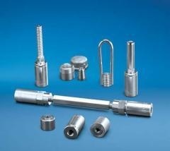
Whilst a bit off track to the OP's question, but somewhat interesting in that you can 'hand torque' barrier cable tendons using a GRABB-IT device that is patented and manufactured by Precision-Hayes from Texas. It is the long component in the middle of this photo:

image_ovydib.jpg


It uses two threaded barrel chucks connected to a opposing thread connecting stem for intermediate stressing points, and they also have end devices that connect/embed into the supporting structure and enable preload of the strand. Long cables where elongations exceed the adjustment length available within the threaded stem is accomplished via attaching additional threaded stems in a male/female arrangement.

We have used them in the past for 'barrier cables', and a few weeks back to repair severed strands to precast planks. It takes a big calibrated torque wrench (like 36" long) to preload a 1/2" dia strand to 25 kips. Not that you would preload a barrier cable to much a high magnitude.

Sorry, OP, this does not help you directly.
 
JTMergens:
I think Jdgengineer has done a very nice job, well reasoned, of presenting an approach to designing these cable railing systems. Along with some of the literature and testing from some of the product suppliers, you should be able to put together a design package which you can sell the most AHJ’s.

However sexy homeowners, Architects and deck designers, et.al., think these cable railing systems are, they are often poorly designed and built. The reason for handrails/guardrails and the entire railing system is to keep people from falling off the deck or other elevated surfaces. Given that, the AHJ’s who object to these systems are asking, then why would we provide a ladder rung system for people to climb up to the top, to the guardrail, so they could fall off?
 
jdgengineer said:
I typically design the cables for a load of 50 lb load applied over a 12"x12" region as required in section 4.5.1 of ASCE 7-10 for intermediate rails / panel fillers. I simplify this to a 12.5 lb load point load per cable (with 3" oc spacing) and set the deflection of the cable to not exceed 1/2 the total deflection that would be allowed stay under 4" sphere. (i.e. 3" oc cables would have 1/2" max deflection).

How are you calculating the deflection of the cables?
 
Agree with jdgengineer....set the cables so that deflection does not allow 4" sphere to pass....everything else is just analysis. If cable tension causes posts to be larger than wanted, decrease spacing of the cables and then you can allow more deflection (less tension).
 
Ingenuity said:
It takes a big calibrated torque wrench (like 36" long)

Guess I should have clarified. You can't hand crank those except for with a giant wrench. [bigsmile]
 
I don't typically calculate the deflection of the cable. Typically, I have designed the posts for the cable rail system but the cable system has been provided by the manufacturer. The systems I have done have all been for single family homes.

However, if you wanted to you could fairly easily. The easiest approach I think would be to set the maximum deflection and solve for minimum area of cable. I would think the process would be:

1) Set cable deflection to maximum allowable to meet 4" sphere requirement based on infill loading.

2) use cable geometry with assumed deflection to solve for cable forces.

3) calculate required cable area based on PL/AE using total length of cable and intermediate post spacing.
 
Norm at Skyline:

In my experience a 2"x2"x1/4" SS or MS post will deflect up to 1/2" on a 42" high rail system at 200 lbs cable tension at 3" centers. I have never seen a small steel or aluminum post that can meet those forces and not deflect to an unacceptable level.Perhaps a 3x3 or 4x4 will approach that kind of force without undue deflection. It is the reason most manufacturers say tighten until "taut" as the standard which is a joke.
 
Kids climb horizontal things... just a caution.

Dik
 
Norm123 said:
In my experience a 2"x2"x1/4" SS or MS post will deflect up to 1/2" on a 42" high rail system at 200 lbs cable tension at 3" centers. I have never seen a small steel or aluminum post that can meet those forces and not deflect to an unacceptable level.Perhaps a 3x3 or 4x4 will approach that kind of force without undue deflection. It is the reason most manufacturers say tighten until "taut" as the standard which is a joke.

Exactly why I refuse to even design cable railing posts. It is not possible in a residential setting to meet all design criteria unless everything is steel and too big for most architect's taste. Most in our area just use standard wood framing with 6x6 end posts. The cables always slacken over time as the wood shrinks and creeps under the sustained loading.
 
I get asked to do cable railing in both commercial and residential applications. I even did cable railing in my house. My philosophy has always been, if you can afford cable, you can afford some extra steel or larger wood members if required. Also, I always specify that re-tensioning is required at 6 months, 12 months, and then every 2 years thereafter. Sure it's extra maintenance, but at least they are going back and making sure the cables are still good.

Providing a solid toe-kick and a steel top rail are the key to resolving the forces. If a wood top rail is requested, I usually will have the contractor notch out the bottom of the top rail for fit of 1/2" steel bar that is then screwed in to the wood using shorter SDS screws. It's a hy-brid type of application, but it has worked out well so far. On occasion an owner doesn't want a toe-kick, but just cables, forces have to be resolved through screws/bolts at that point. I don't necessarily like it, but I can get things to pencil out.
 
Check out the information from this supplier.
They have done some testing and derived several equations. Long story short is that I design the posts for a 400 lb pretension load and (4) cables for 460 lb. The 460 lb load is from trying to pass a 4" sphere through the cables. Cables are spaced at 3" and have a top rail.
 
Status
Not open for further replies.

Part and Inventory Search

Sponsor