Continue to Site

Eng-Tips is the largest engineering community on the Internet

Intelligent Work Forums for Engineering Professionals

  • Congratulations waross on being selected by the Eng-Tips community for having the most helpful posts in the forums last week. Way to Go!

Calculate force required to crush a tube 5

Status
Not open for further replies.

smithtasticness

Industrial
Nov 18, 2020
13
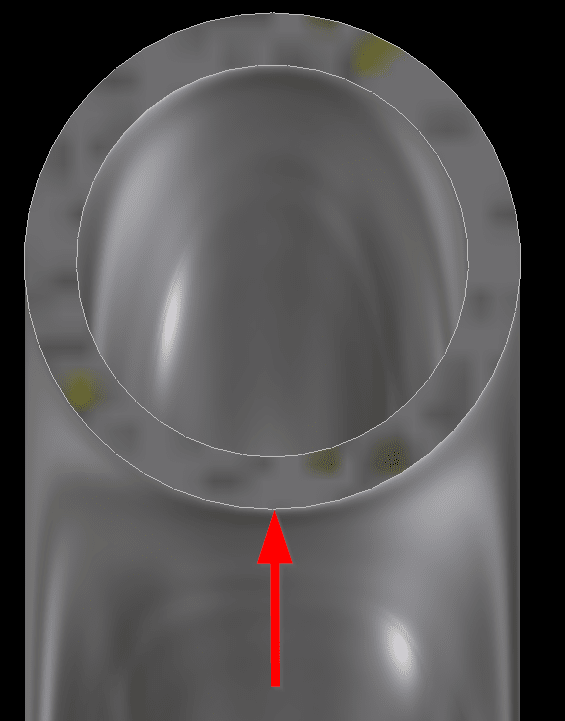
image_mqmqbg.png


I have some tube (see above & ignore the fact that it's bent for now) and I'm trying to find out how I can calculate the force or load it'll take before the tube crushes.

I can't seem to find this anywhere but I think I might be looking in the wrong places. I've found plenty of buckling formula but I'm almost certain that those are either for compressive strength or for buckling along a given length. I think what I need is much simpler, but I'm totally lost on this one. I'm hoping someone here might be able to point me in the right direction.

I'm assuming that realistically I should only need the cross-section properties and material properties to be able to figure it out but at the moment I cannot see the light.

Thanks in advance.
 
Replies continue below

Recommended for you

See that's where I fall down. I can use Inventor for FEA but not only do I not trust it, but I'd also like to be able to figure this one out manually.

I'll google non-linear FEA and see if I can find anything though. Cheers.
 
Nonlinear FEA will be the most accurate but you can try solving this as curved beam. Check Roark’s Formulas for Stress and Strain.
 
Thanks. I'll look into them both. Think I've already been via Roark's formulas but I'm not sure they were what I was looking for.
 
Check the chapter 9 "Curved Beams". In the text and in the table 9.2 ("Formulas for circular rings") you will find necessary equations.
 
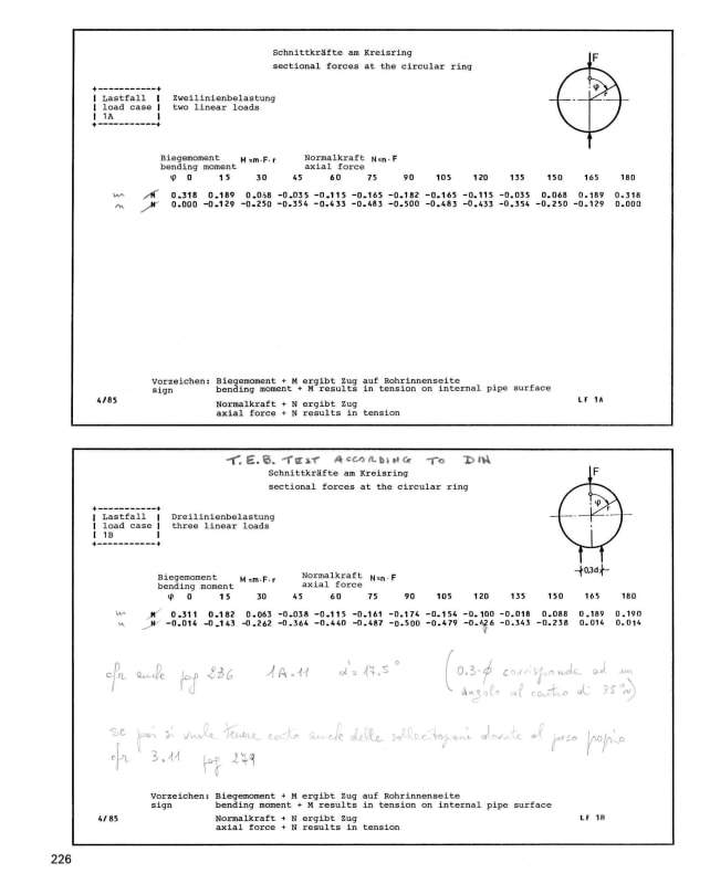
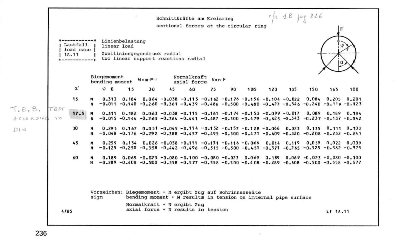
just a bit different approach (excerpt from "Structural analysis of buried pipes" - Hornung/Kittel - Bauverlag - 1989

ring_01_hx2zjg.jpg


ring_02_nww1cd.jpg


ring_03_kgsjjx.jpg


Further details and explanation in "Structural Mechanics of Buried Pipes" - Watkins/Anderson - CRC Press - 2000
 
Roark, 7th ed, table 9.2, case 1 ... Mmax = 0.3183*MR*(1-a), a, alpha, = I/(A*R^2) = (rho/R)^2
compare to plastic bending allowable.

Answer is IMO approximate as it is not designed to answer the question "load to crush the tube", though once the critical section goes plastic ... the end is nigh.

Do you have a press ? why not "suck it and see" ?

another day in paradise, or is paradise one day closer ?
 
Thanks, everyone. Lots (more) to look at.

rb1957 I don't have a press local to me atm as I'm working from home :'(... But might be something I can look into once Covid has buggered off enough that I can return to work.

Cheers.
 
I think you need to define what it is you're trying to solve first as it's not clear.

Is this a uniform external force like being submerged at the bottom of the ocean with only 1 bars inside?

Is it a long piece or a short piece where the tube is kept open?
Is it a span between two point supports or uniformly supported on one side (like being laid on a flat plate or a concrete pad.

Is it a point load?
Is it a point load one side and a flat plat the other side?

Is it being crushed by two flat plates ( like a vice?)

does it have any other bending forces going on ? Or axial or compressive forces?

Does it have internal pressure?

Is there ANY existing ovality

Only when you've figure out all that can you try and work anything out.

Remember - More details = better answers
Also: If you get a response it's polite to respond to it.
 
LittleInch. There's actually a fair bit going on with this, I was trying to simplify it and break it down into smaller calcs in the hope of getting a rough idea if my design is suitable or not.

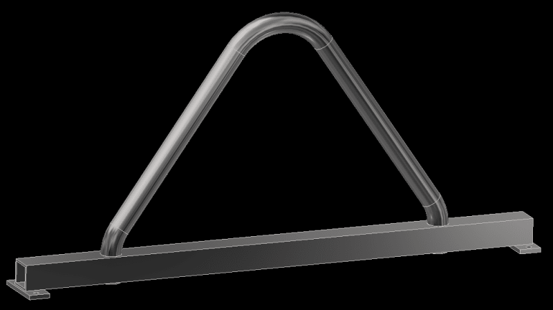
The whole thing looks like this...
image_nbonz0.png


The SHS is basically a spreader beam which I am happy is strong enough based on my calcs of that as a spreader beam. The pipe is acting as a large rope/hook loop basically. It will see load on the underside of the top bend. As the top is formed obviously it will have ovality already.

I'm fairly confident that the pipe in tension is more than strong enough so really was just wanting to figure out if it would crush at the top where the point load will be.
 
this is much different to what I thought you were doing (I thought you wanted to crush the tube).

bending tube is quite specialised, if you want nice looking bends. If think you want some sort of pipe-bender ... like maybe what they use for electrical conduit ... plumbing feels too heavy duty.

Sorry ... must read the post ... fully !
The maximum load on the bend would be a function of how concentrated the load is, and how you define maximum ... when the part is starting to deform, or when the part is in two pieces.
Then of course the useful load would depend on the SF you apply to this allowable load.
I guess you could develop a moment in the bend from symmetry, and so bending stress in the pipe ?

another day in paradise, or is paradise one day closer ?
 
No, I'm not trying to bend the tube, the tube will be bent already. I'm using the bent tube to lift a load using the above, welded assembly.
 
I thought as rb1957. To me you have to consider the shear stress of the lifting load (in plane of the circular section) plus the longitudinal stresses (orthogonal to the circular section) : may be you can super-impose two conditions as per Roark's formulas in table 13.2. Good luck (by hand calcs)
 
Why not use solid bar?

----------------------------------------

The Help for this program was created in Windows Help format, which depends on a feature that isn't included in this version of Windows.
 
Oh man, that's a FEA job. all other calculations as realtively simjlistic and amke some assumptions about the tube that you don't have.

Also there a massive difference between a rope / sling which is a distributed load and "hook" which implies really high point loads.

But I don't know why you're bothered. if the tube flattens then so what? You haven't got flow through it and it won't break because of that. Your failure modes must surely be in tension failure of the tube or failure at those little 45 degree elbows. I don't know why you don't just weld the tube at an angle and forget about those little bends with their stress concentration factors.

If anything a little bit of flattening at the hook point could be a good early warning that your tube is overloaded...

This really just goes into the test it to destruction mode then apply a SF of about 3. IMHO.


Remember - More details = better answers
Also: If you get a response it's polite to respond to it.
 
FEA ? "surely" the upper curved piece is symmetrical, so consider 1/2 as a cantilever ... a curved cantilever may be, but still something we can approach with hand calcs ?

sure this isn't looking at collapse of the CL section but it should be at least close to the answer ?

another day in paradise, or is paradise one day closer ?
 
Thanks again, everyone.

dgallup, only reason not to use solid bar is to save weight. This lifting bar will be bolted to something that floats.

I knew it was going to come back to FEA. Looks like I'm going to need to get better at hand calc FEA. Something I've not done before.

LittleInch, the tube goes through the box and is fully welded top and bottom to provide greater strength. Though I understand what you're saying, the loads this is taking aren't really sufficient enough to worry about those stress points.
 
Could you pack the inside with sand?

Or epoxy and let it go off?

Or grout? Or sand and cement and water

You only need to fill the small bent part at the top.

Remember - More details = better answers
Also: If you get a response it's polite to respond to it.
 
Status
Not open for further replies.

Part and Inventory Search

Sponsor