Continue to Site

Eng-Tips is the largest engineering community on the Internet

Intelligent Work Forums for Engineering Professionals

  • Congratulations GregLocock on being selected by the Eng-Tips community for having the most helpful posts in the forums last week. Way to Go!

Calculating flow based on power consumption

Status
Not open for further replies.

c991257

Industrial
Sep 26, 2019
5
Hi.

I have a pumping system with say 10 pumps (pumping from the same tank) connecting to a manifold which sends the water to some other tanks.

If the pressure on the manifold is known, and I measure the power consumption on each pump, then I should be able to read the flow rate on each pump on the pump curve. Adding the flow rates should give me the total flow. However the manufacturer of the pump says I can't count on that, but he can't explain why.

Can anyone explain why that is?

/Moeller
 
Replies continue below

Recommended for you

c991257:
Are the 10 pumps connected in series or parallel? If they are in series then the flow rate will be same and in parallel you can add flow rates. Since, you are trying to add the flow rate, I think your 10 pumps are in parallel. The reason why you can't simply add the flow rates because there are losses you should consider. Theoretically, you can add them by making assumptions but not practically.
 
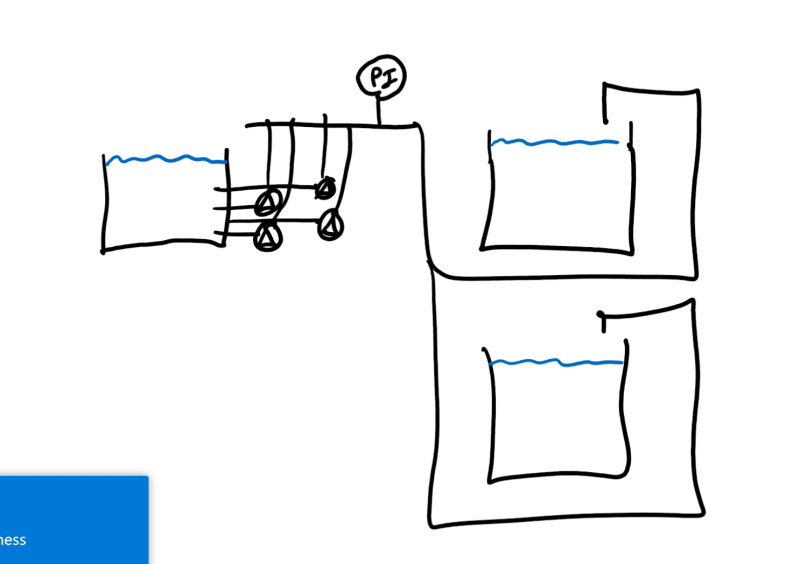
Annotation_2019-09-27_080722_z4r10k.png


The setup is something like this (only four pumps shown).
 
Can be done as you describe but the accuracy is low. If you want flow there are many other much more accurate methods.

If you've got pump curves and you know the inlet head from the tank then you can estimate flow.

Now how accurate your curve is is a big question.

Read this recent post on a similar subject especially the post by artisi.


Remember - More details = better answers
Also: If you get a response it's polite to respond to it.
 
Measure the flow, there are many ways to achieve this, it's not rocket science.
Inline orifice plate, clamp on doppler device, pieto tube.
Cannot understand, a company installing 10 pumps in a system and not spending a piddly amount on some type of measuring equipment.

It is a capital mistake to theorise before one has data. Insensibly one begins to twist facts to suit theories, instead of theories to suit facts. (Sherlock Holmes - A Scandal in Bohemia.)
 
Or just measure the level in the reception tank(s) over a fixed period of time??

Remember - More details = better answers
Also: If you get a response it's polite to respond to it.
 
@Artsi,

the problem is our piping is rather large (ø630 to ø1200) and clamp-on flow meters typically require 15 DN lengths straight pipe for accurate measurements. I don't have that at all.

A 10 pump system flows around 4000 m3 per hour, and that is a small-medium size system for us.


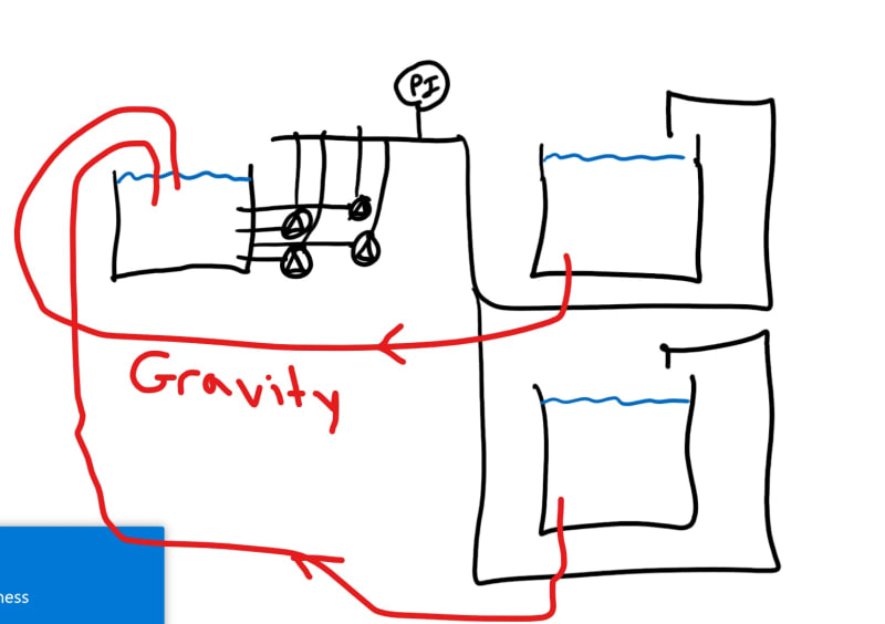
@LittleInch. I can see I forgot to draw the returnpipe.
InkedAnnotation_2019-09-27_080722_LI_p8cds2.jpg

Since we have a reasonably fixed waterlevel in the two tanks on the right side I can't measure any changes there.

A colleague also told me that the voltage might not be as expected at the pumps, which means that the amp usage can't be directly transferred to the pump curve.
 
Pitot tube.

It is a capital mistake to theorise before one has data. Insensibly one begins to twist facts to suit theories, instead of theories to suit facts. (Sherlock Holmes - A Scandal in Bohemia.)
 
From the diagram the best place for a flow measurement would be just after the drain where the flow should be fairly laminar, but it's probably inconvenient.

It seems reasonable to look at power vs pressure to determine flow as the other place power would go is into heat in the pump motor and into the fluid. If the motor and the fluid temperatures don't change the only other place should be flow. Obviously the precision and the system response won't be great, but it is cheap. It is important to measure the pressure at the pump or to account for any pressure head.
 
If this is truly a gravity drain and you are able to calculate the pressure drop of the drain pipe, you are theoretically able to correlate the flow in the drain to the height of the tank.
 
@artisi: Doesn't the pitot tube require a certain pipe length for laminar flow? Any Idea what it costs when flow is 4000 m3/hrs and pipe dia is 630 mm?

@3DDave: The pipe is somewhat higher up so it sucks in some air.

@Danschwind: 100% gravity. 300 mm difference in water level. Bernoulli?
 
Probably it does need x lengths of straight pipe, suggest you establish how much and then compare what there is on site.

It is a capital mistake to theorise before one has data. Insensibly one begins to twist facts to suit theories, instead of theories to suit facts. (Sherlock Holmes - A Scandal in Bohemia.)
 
c991257,

Try applying Bernoulli with the pressure drop you calculate for the drain pipe and see if this number is wildly off or if it makes sense.
 
Thanks all. I'll have a better engineer than me look at it on Monday.

Everybody, enjoy your weekend when you get there.

 
Like I said on the other thread I linked to - it all depends where you are on the pump curve. If it's fairly flat you're looking at +/- 20% or more. On a steeper part then maybe closer to +/- 10%.

Even if you've not got a lot of straight length any flow meter or insertion meter will get you to better than 5%.

How accurate do you want to be?

Also 10 parallel units means your "best" pump could be doing 30% more flow than the "worst" pump depending on other losses, variance in pump and motor etc.

If you want to use power to try and estimate flow then yes, you need to do some actual running voltage checks at the motor by the electrical tech

Remember - More details = better answers
Also: If you get a response it's polite to respond to it.
 
The total flow rate developed may not be a simple addition of the individual flow rates developed especially in the cases, where the pumps do not have similar characteristic curves. Are they all similar "sister pumps"?
 
Status
Not open for further replies.

Part and Inventory Search

Sponsor